www.ti.com
Code Security Module (CSM)
49
SPRUI07–March 2020
Submit Documentation Feedback
Copyright © 2020, Texas Instruments Incorporated
System Control and Interrupts
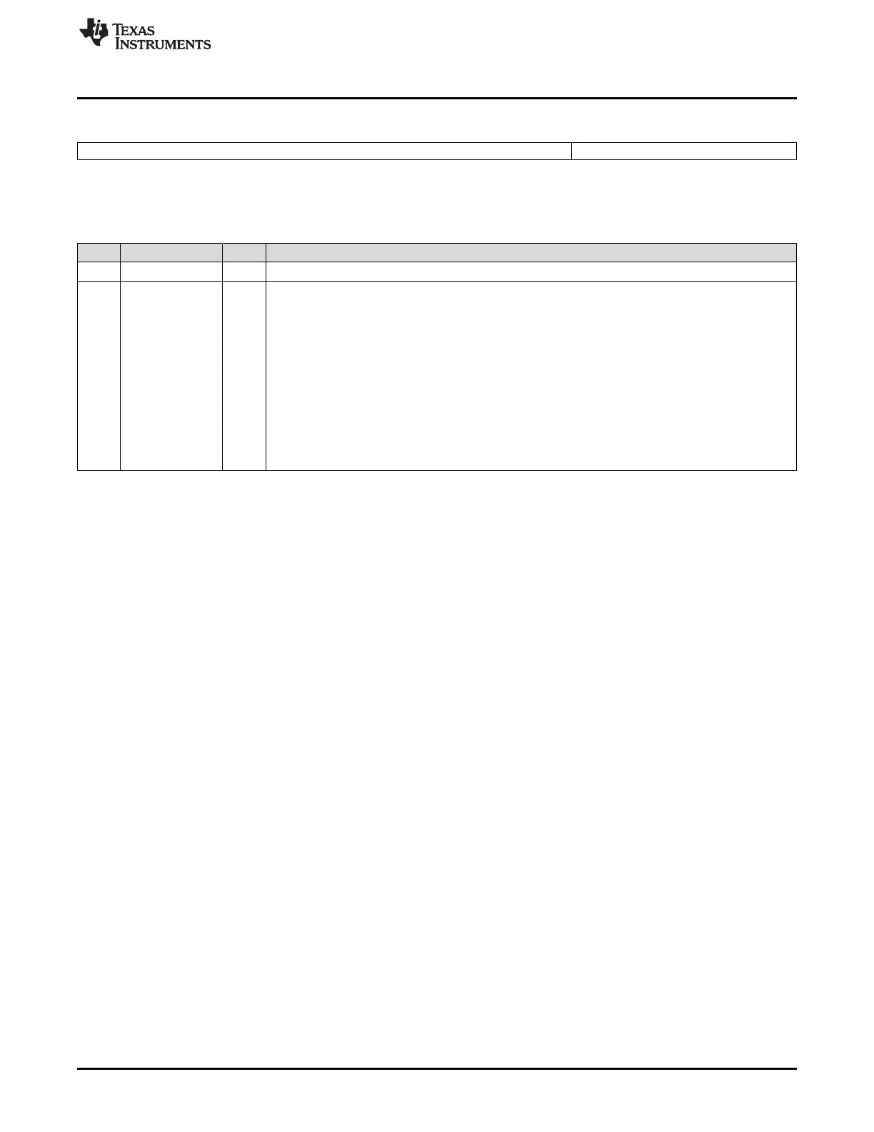
Figure 1-10. OTP Wait-State Register (FOTPWAIT)
15 5 4 0
Reserved OTPWAIT
R-0 R/W-0x1F
LEGEND: R/W = Read/Write; R = Read only; -n = value after reset
(1)
This register is EALLOW protected. See Section 1.5.2 for more information.
(2)
This register is protected by the Code Security Module (CSM). See Section 1.2 for more information.
(3)
When writing to this register, follow the procedure described in Section 1.1.3.4.
Table 1-8. OTP Wait-State Register (FOTPWAIT) Field Descriptions
Bit(s) Field Value Description
(1) (2) (3)
15-5 Reserved 0 Reserved
4-0 OTPWAIT OTP Read Wait States. These register bits specify the number of wait states for a read operation in
CPU clock cycles (1..31 SYSCLKOUT cycles) to the OTP. See CPU Read Or Fetch Access From
flash/OTP section for details. There is no PAGE mode in the OTP.
OTPWAIT must be set greater than 0. That is, a minimum of 1 wait state must be used. See the
device-specific data manual for the minimum time required for an OTP access.
00000 Illegal value. OTPWAIT must be set to 1 or greater.
00001 One wait state will be used each OTP access for a total of two SYSCLKOUT cycles per access.
00010 Two wait states will be used for each OTP access for a total of three SYSCLKOUT cycles per access.
00011 Three wait states will be used for each OTP access for a total of four SYSCLKOUT cycles per access.
. . . . . .
11111 31 wait states will be used for an OTP access for a total of 32 SYSCLKOUT cycles per access.
1.2 Code Security Module (CSM)
The code security module (CSM) is a security feature incorporated in 28x devices. It prevents
access/visibility to on-chip memory to unauthorized persons — that is, it prevents duplication/reverse
engineering of proprietary code.
The word secure means access to on-chip memory is protected. The word unsecure means access to on-
chip secure memory is not protected — that is, the contents of the memory could be read by any means
(through a debugging tool such as Code Composer Studio™, for example).
1.2.1 Functional Description
The security module restricts the CPU access to certain on-chip memory without interrupting or stalling
CPU execution. When a read occurs to a protected memory location, the read returns a zero value and
CPU execution continues with the next instruction. This, in effect, blocks read and write access to various
memories through the JTAG port or external peripherals. Security is defined with respect to the access of
on-chip memory and prevents unauthorized copying of proprietary code or data.
The device is secure when CPU access to the on-chip secure memory locations is restricted. When
secure, two levels of protection are possible, depending on where the program counter is currently
pointing. If code is currently running from inside secure memory, only an access through JTAG is blocked
(that is, through the emulator). This allows secure code to access secure data. Conversely, if code is
running from nonsecure memory, all accesses to secure memories are blocked. User code can
dynamically jump in and out of secure memory, thereby allowing secure function calls from nonsecure
memory. Similarly, interrupt service routines can be placed in secure memory, even if the main program
loop is run from nonsecure memory.
Security is protected by a password of 128-bits of data (eight 16-bit words) that is used to secure or
unsecure the device. This password is stored at the end of flash in 8 words referred to as the password
locations.
The device is unsecured by executing the password match flow (PMF), described Section 1.2.3.2.
Table 1-9 shows the levels of security.
 Loading...