www.ti.com
Clocking and System Control
85
SPRUI07–March 2020
Submit Documentation Feedback
Copyright © 2020, Texas Instruments Incorporated
System Control and Interrupts
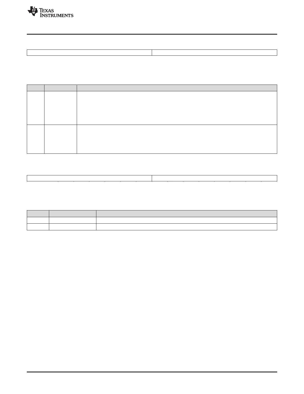
Figure 1-38. TIMERxTPR Register (x = 0, 1, 2)
15 8 7 0
PSC TDDR
R-0 R/W-0
LEGEND: R/W = Read/Write; R = Read only; -n = value after reset
Table 1-37. TIMERxTPR Register Field Descriptions
Bits Field Description
15-8 PSC CPU-Timer Prescale Counter. These bits hold the current prescale count for the timer. For every timer clock
source cycle that the PSCH:PSC value is greater than 0, the PSCH:PSC decrements by one. One timer clock
(output of the timer prescaler) cycle after the PSCH:PSC reaches 0, the PSCH:PSC is loaded with the contents
of the TDDRH:TDDR, and the timer counter register (TIMH:TIM) decrements by one. The PSCH:PSC is also
reloaded whenever the timer reload bit (TRB) is set by software. The PSCH:PSC can be checked by reading
the register, but it cannot be set directly. It must get its value from the timer divide-down register
(TDDRH:TDDR). At reset, the PSCH:PSC is set to 0.
7-0 TDDR CPU-Timer Divide-Down. Every (TDDRH:TDDR + 1) timer clock source cycles, the timer counter register
(TIMH:TIM) decrements by one. At reset, the TDDRH:TDDR bits are cleared to 0. To increase the overall timer
count by an integer factor, write this factor minus one to the TDDRH:TDDR bits. When the prescaler counter
(PSCH:PSC) value is 0, one timer clock source cycle later, the contents of the TDDRH:TDDR reload the
PSCH:PSC, and the TIMH:TIM decrements by one. TDDRH:TDDR also reloads the PSCH:PSC whenever the
timer reload bit (TRB) is set by software.
Figure 1-39. TIMERxTPRH Register (x = 0, 1, 2)
15 8 7 0
PSCH TDDRH
R-0 R/W-0
LEGEND: R/W = Read/Write; R = Read only; -n = value after reset
Table 1-38. TIMERxTPRH Register Field Descriptions
Bits Field Description
15-8 PSCH See description of TIMERxTPR.
7-0 TDDRH See description of TIMERxTPR.
 Loading...