Clr
Set
Latch
QFRC:PCE
PCE
QCLR:PCE
QFLG:PCE
QEINT:PCE
QCLR:UTO
QFRC:UTO
QEINT:UTO
set
Latch
clr
UTO
QFLG:UTO
0
1
0
Pulse
generator
when
input=1
QFLG:INT
Latch
Set Clr
QCLR:INT
EQEPxINT
eQEP Interrupt Structure
www.ti.com
410
SPRUI07–March 2020
Submit Documentation Feedback
Copyright © 2020, Texas Instruments Incorporated
Enhanced Quadrature Encoder Pulse (eQEP)
6.9 eQEP Interrupt Structure
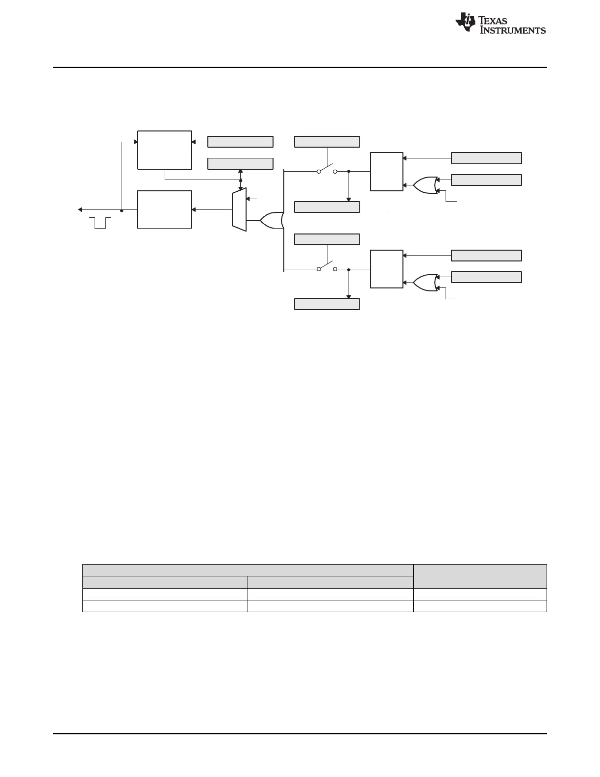
Figure 6-20 shows how the interrupt mechanism works in the EQEP module.
Figure 6-20. EQEP Interrupt Generation
Eleven interrupt events (PCE, PHE, QDC, WTO, PCU, PCO, PCR, PCM, SEL, IEL and UTO) can be
generated. The interrupt control register (QEINT) is used to enable/disable individual interrupt event
sources. The interrupt flag register (QFLG) indicates if any interrupt event has been latched and contains
the global interrupt flag bit (INT).
An Interrupt pulse is generated to PIE when:
a. Interrupt is enabled for eQEP event inside QEINT register
b. Interrupt flag for eQEP event inside QFLG register is set, and
c. Global interrupt status flag bit QFLG[INT] had been cleared for previously generated interrupt event.
The interrupt service routine will need to clear the global interrupt flag bit and the serviced event, via
the interrupt clear register (QCLR), before any other interrupt pulses are generated.If either flags inside
the QFLG register are not cleared, further interrupt event will not generate interrupt to PIE. You can
force an interrupt event by way of the interrupt force register (QFRC), which is useful for test purposes.
6.10 eQEP Registers
This section describes the Enhanced Quadrature Encoder Pulse Registers.
6.10.1 eQEP Base Addresses
Table 6-3. EQEP Base Address Table
Bit Field Name
Base Address
Instance Structure
EQep1Regs EQEP_REGS 0x0000_6B00
EQep2Regs EQEP_REGS 0x0000_6B40
 Loading...