www.ti.com
ADC Registers
489
SPRUI07–March 2020
Submit Documentation Feedback
Copyright © 2020, Texas Instruments Incorporated
Analog-to-Digital Converter (ADC)
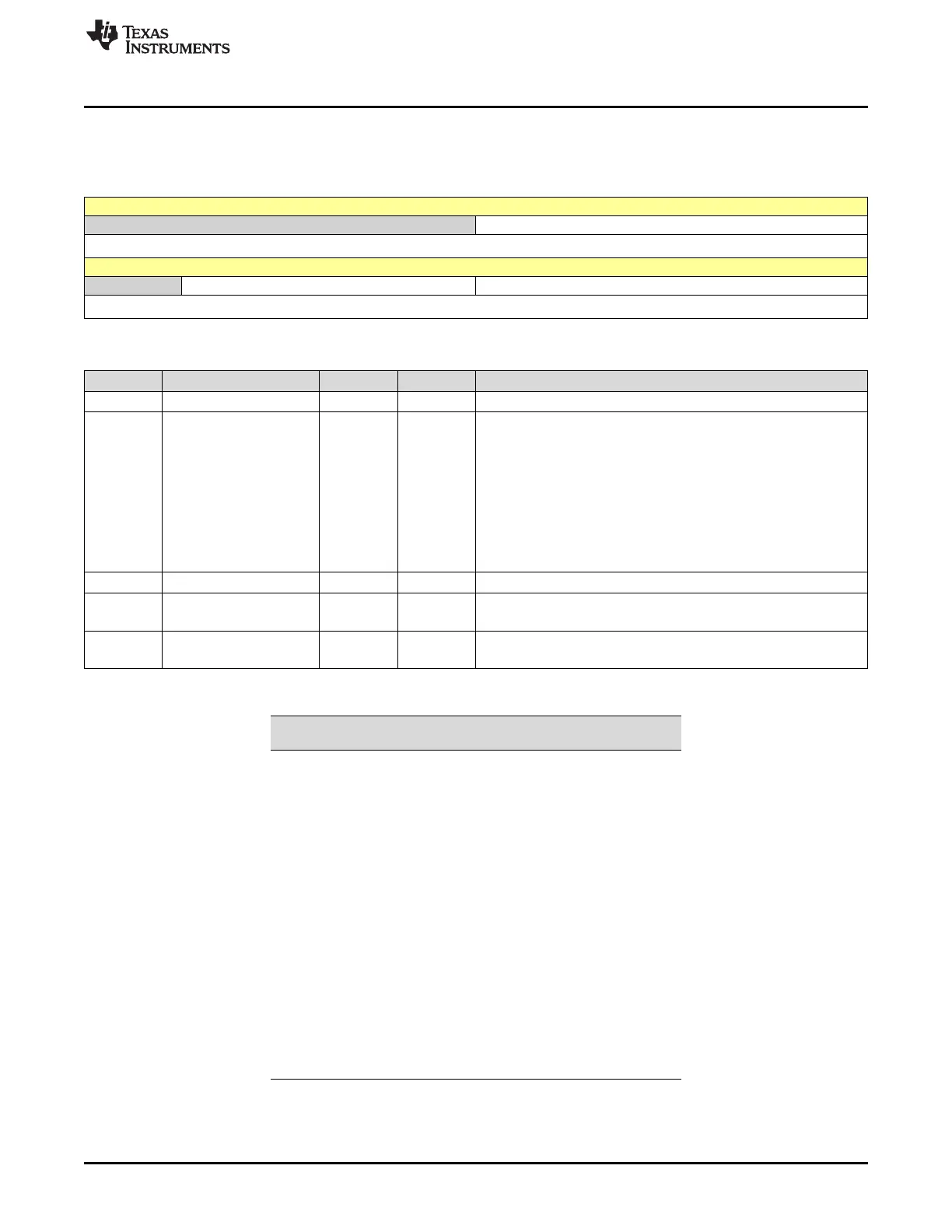
7.4.8 ADCASEQSR Register (Offset = 7h) [reset = 0h]
ADCASEQSR is shown in Figure 7-22 and described in Table 7-19.
Figure 7-22. ADCASEQSR Register
15 14 13 12 11 10 9 8
RESERVED SEQ_CNTR[3:0]
R-0h R-0h
7 6 5 4 3 2 1 0
RESERVED SEQ2_STATE SEQ1_STATE
R-0h R-0h R-0h
Table 7-19. ADCASEQSR Register Field Descriptions
Bit Field Type Reset Description
15-12 RESERVED R 0h Reads return a zero. Writes have no effect.
11-8 SEQ_CNTR[3:0] R 0h Sequencing counter status bits. The SEQ_CNTRn 4-bit status field is
used by SEQ1, SEQ2, and the cascaded sequencer. SEQ2 is
irrelevant in cascaded mode. The Sequencer Counter bit field,
SEQ_CNTR[3:0], is initialized to the value in MAX_CONV at the start
of a conversion sequence. After each conversion (or a pair of
conversions in simultaneous sampling mode) in an auto conversion
sequence, the Sequencer Counter decreases by 1.The SEQ_CNTR
bits can be read at any time during the countdown process to check
status of the sequencer. This value, together with the SEQ1 and
SEQ2 busy bits, uniquely identifies the progress or state of the
active sequencer at any point in time. See Table 7-20.
7 RESERVED R 0h Reads return a zero. Writes have no effect.
6-4 SEQ2_STATE R 0h
SEQ2_STATE and SEQ1_STATE bit fields are the pointers of SEQ2
and SEQ1, respectively.
3-0 SEQ1_STATE R 0h
SEQ2_STATE and SEQ1_STATE bit fields are the pointers of SEQ2
and SEQ1, respectively.
Table 7-20. State of Active Sequencer
SEQ_CNTR (read only)
Number of conversions
remaining
0000 1 or 0, depending on the busy bit
0001 2
0010 3
0011 4
0100 5
0101 6
0110 7
0111 8
1000 9
1001 10
1010 11
1011 12
1100 13
1101 14
1110 15
1111 16
 Loading...