S
1
1 1 1 1 0 x x
7
x x x x x x x xACK
11
8
ACK
1
Data
n
ACK
1
P
1
x x = 2 MSBs
R/W
8 LSBs of slave address
S
7 bits of slave address
R/W ACK Data ACK Data ACK P
7 n n
1 1 1 1 1 1
x x x x x x x
SDA
SCL
MSB
Acknowledgement
bit from slave
(No-)Acknowledgement
bit from receiver
1 2 7 8 9 1 2 8 9
Slave address ACK
START
condition (S)
STOP
condition (P)
R/W
ACK Data
I2C Module Operational Details
www.ti.com
624
SPRUI07–March 2020
Submit Documentation Feedback
Copyright © 2020, Texas Instruments Incorporated
Inter-Integrated Circuit Module (I2C)
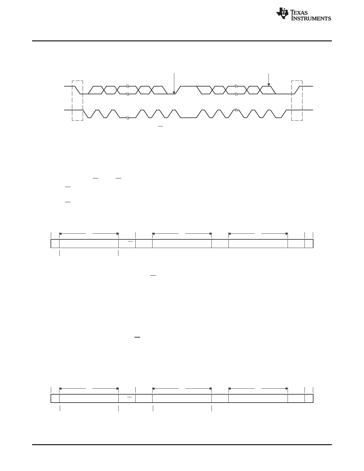
Figure 11-7. I2C Module Data Transfer (7-Bit Addressing with 8-bit Data Configuration Shown)
11.3.5.1 7-Bit Addressing Format
The 7-bit addressing format is the default format after reset. Disabling expanded address (I2CMDR.XA =
0) and free data format (I2CMDR.FDF = 0) enables 7-bit addressing format.
In this format (see Figure 11-8), the first byte after a START condition (S) consists of a 7-bit slave address
followed by a R/W bit. R/W determines the direction of the data:
• R/W = 0: The I2C master writes (transmits) data to the addressed slave. This can be achieved by
setting I2CMDR.TRX = 1 (Transmitter mode)
• R/W = 1: The I2C master reads (receives) data from the slave. This can be achieved by setting
I2CMDR.TRX = 0 (Receiver mode)
Figure 11-8. I2C Module 7-Bit Addressing Format (FDF = 0, XA = 0 in I2CMDR)
An extra clock cycle dedicated for acknowledgment (ACK) is inserted after each byte. If the ACK bit is
inserted by the slave after the first byte from the master, it is followed by n bits of data from the transmitter
(master or slave, depending on the R/W bit). n is a number from 1 to 8 determined by the bit count (BC)
field of I2CMDR. After the data bits have been transferred, the receiver inserts an ACK bit.
11.3.5.2 10-Bit Addressing Format
The 10-bit addressing format can be enabled by setting expanded address (I2CMDR.XA = 1) and
disabling free data format (I2CMDR.FDF = 0).
The 10-bit addressing format (see Figure 11-9) is similar to the 7-bit addressing format, but the master
sends the slave address in two separate byte transfers. The first byte consists of 11110b, the two MSBs of
the 10-bit slave address, and R/W. The second byte is the remaining 8 bits of the 10-bit slave address.
The slave must send acknowledgment after each of the two byte transfers. Once the master has written
the second byte to the slave, the master can either write data or use a repeated START condition to
change the data direction. For more details about using 10-bit addressing, see the NXP Semiconductors
I2C bus specification.
Figure 11-9. I2C Module 10-Bit Addressing Format (FDF = 0, XA = 1 in I2CMDR)
11.3.5.3 Free Data Format
The free data format can be enabled by setting I2CMDR. FDF = 1.
 Loading...