1
0
XCLKOUT
/2
XTIMCLK
1
0
/2
C28x
CPU
XINTCNF2
(CLKMODE)
XINTCNF2(XTIMCLK)
DefaultValueafterreset
SYSCLKOUT
XINTCNF2
(CLKOFF)
www.ti.com
Clocking and System Control
69
SPRUI07–March 2020
Submit Documentation Feedback
Copyright © 2020, Texas Instruments Incorporated
System Control and Interrupts
The following list describes the behavior of the missing clock detect logic in various operating modes:
• PLL by-pass mode
When the PLL control register is set to 0x0000, the PLL is by-passed. Depending on the state of the
PLLSTS[DIVSEL] bit, OSCCLK, OSCCLK/2, or OSCCLK/4 is connected directly to the CPU's input
clock, CLKIN. If the OSCCLK is detected as missing, the device will automatically switch to the PLL,
set the missing clock detect status bit, and generate a missing clock reset. The device will now run at
the PLL limp mode frequency or one-half of the PLL limp mode frequency.
• PLL enabled mode
When the PLL control register is non-zero (PLLCR = n, where n ≠ 0x0000), the PLL is enabled. In this
mode, OSCCLK*n, OSCCLK*n/2, or OSCCLK*n/4 is connected to CLKIN of the CPU. If OSCCLK is
detected as missing, the missing clock detect status bit will be set and the device will generate a
missing clock reset. The device will now run at one-half of the PLL limp mode frequency.
• STANDBY low power mode
In this mode, the CLKIN to the CPU is stopped. If a missing input clock is detected, the missing clock
status bit will be set and the device will generate a missing clock reset. If the PLL is in by-pass mode
when this occurs, then one-half of the PLL limp frequency will automatically be routed to the CPU. The
device will now run at the PLL limp mode frequency or at one-half or one-fourth of the PLL limp mode
frequency, depending on the state of the PLLSTS[DIVSEL] bit.
• HALT low power mode
In HALT low power mode, all of the clocks to the device are turned off. When the device comes out of
HALT mode, the oscillator and PLL will power up. The counters that are used to detect a missing input
clock (VCOCLK and OSCCLK) will be enabled only after this power-up has completed. If VCOCLK
counter overflows, the missing clock detect status bit will be set and the device will generate a missing
clock reset. If the PLL is in by-pass mode when the overflow occurs, then one-half of the PLL limp
frequency will automatically be routed to the CPU. The device will now run at the PLL limp mode
frequency or at one-half or one-fourth of the PLL limp mode frequency depending on the state of the
PLLSTS[DIVSEL] bit.
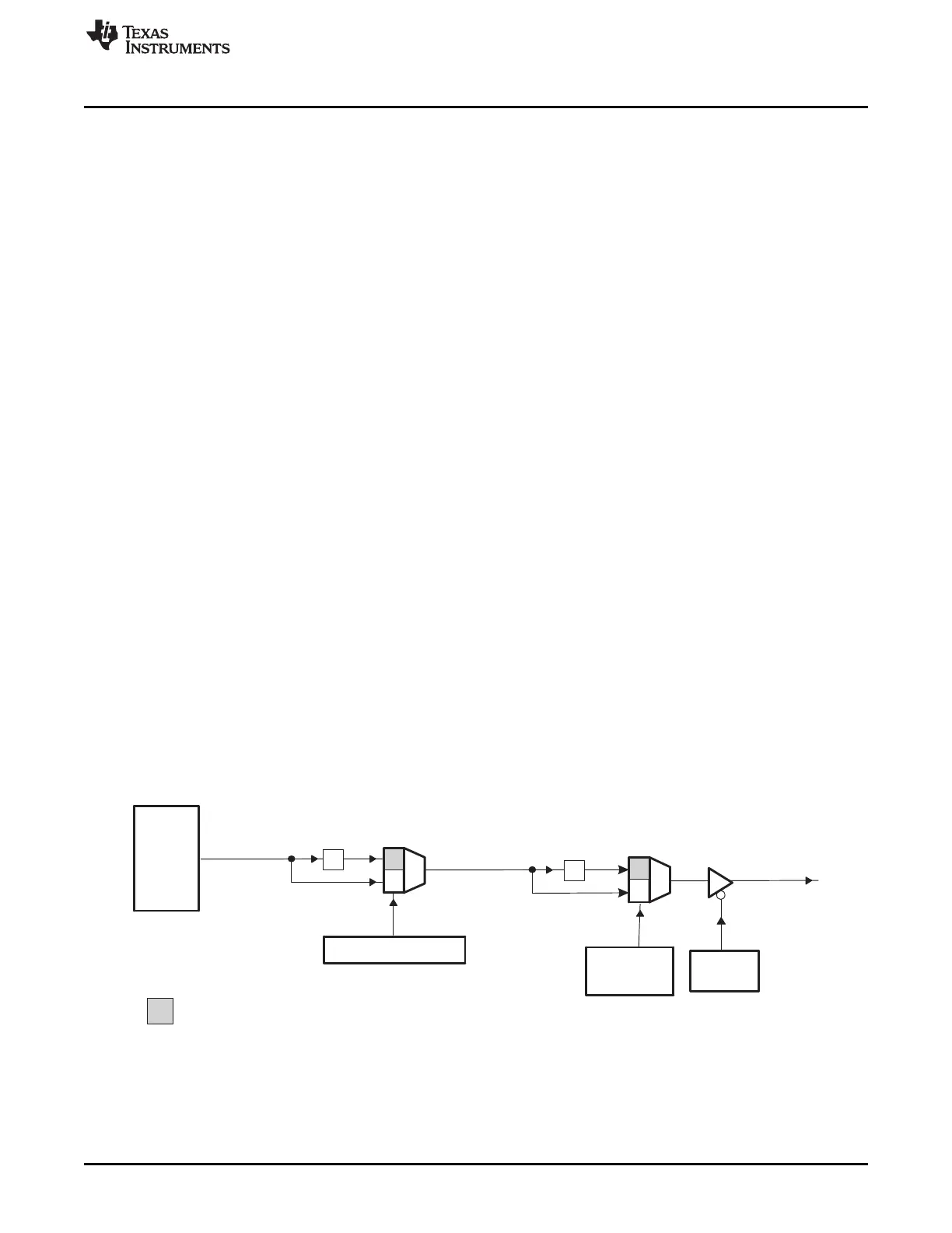
1.3.2.3 XCLKOUT Generation
The XCLKOUT signal is directly derived from the system clock SYSCLKOUT as shown in Figure 1-21.
XCLKOUT can be either equal to, one-half, or one-fourth of SYSCLKOUT. By default, at power-up,
XCLKOUT = SYSCLKOUT/4 or XCLKOUT = OSCCLK/16 . Note that the boot ROM changes
SYSCLKOUT from OSCCLK/4 to OSCCLK/2. Therefore, if the boot ROM has been executed after a reset,
XCLKOUT will be OSCCLK/8.
Figure 1-21. XCLKOUT Generation
The XCLKOUT signal is active when reset is active. Since XCLKOUT should reflect SYSCLKOUT/4 when
reset is low, you can monitor this signal to detect if the device is being properly clocked during debug.
There is no internal pullup or pulldown on the XCLKOUT pin.
If XCLKOUT is not being used, it can be turned off by setting the CLKOFF bit to 1 in the XINTCNF2
register.
 Loading...