GPBDAT
(latch)
GPBCLEAR
GPBTOGGLE
GPBSEL1
Qual
GPBMUX1
SYSCLKOUT
High
Impedance
Output
Control
GPIO32,
GPIO33
Pins
PU
XRS
0
=
Input
,
1
=
Output
Sync
GPBDIR
(latch)
01
11
01
GPBCTRL
2
2
10
Perpheral1input
N/C
(defaultonreset)
GPIO32/33_OUT
(defaultonreset)
GPBPUD
0 = enablePU
1 = disablePU
(disabledafterreset)
async
(asyncdisable
whenlow)
0x
1x
11
10
Peripheral2input
Peripheral3input
GPBSET
(defaultonreset)
3samples
6samples
00
00
XRS
DefaultatReset
External
interrupt
MUX
GPIOXINT6SEL
GPIOXINT7SEL
GPIOXINT5SEL
GPIOXINT4SEL
GPIOXINT3SEL
PIE
GPBDAT (read)
01
Perpheral1output
11
10
Peripheral2output
Peripheral3output
00
01
11
10
Peripheral2outputenable
Peripheral3outputenable
00
SDAA/SCLA (I2Coutputenable)
SDAA/SCLA (I2Cdataout)
GPIO32/33-DIR
www.ti.com
General-Purpose Input/Output (GPIO)
89
SPRUI07–March 2020
Submit Documentation Feedback
Copyright © 2020, Texas Instruments Incorporated
System Control and Interrupts
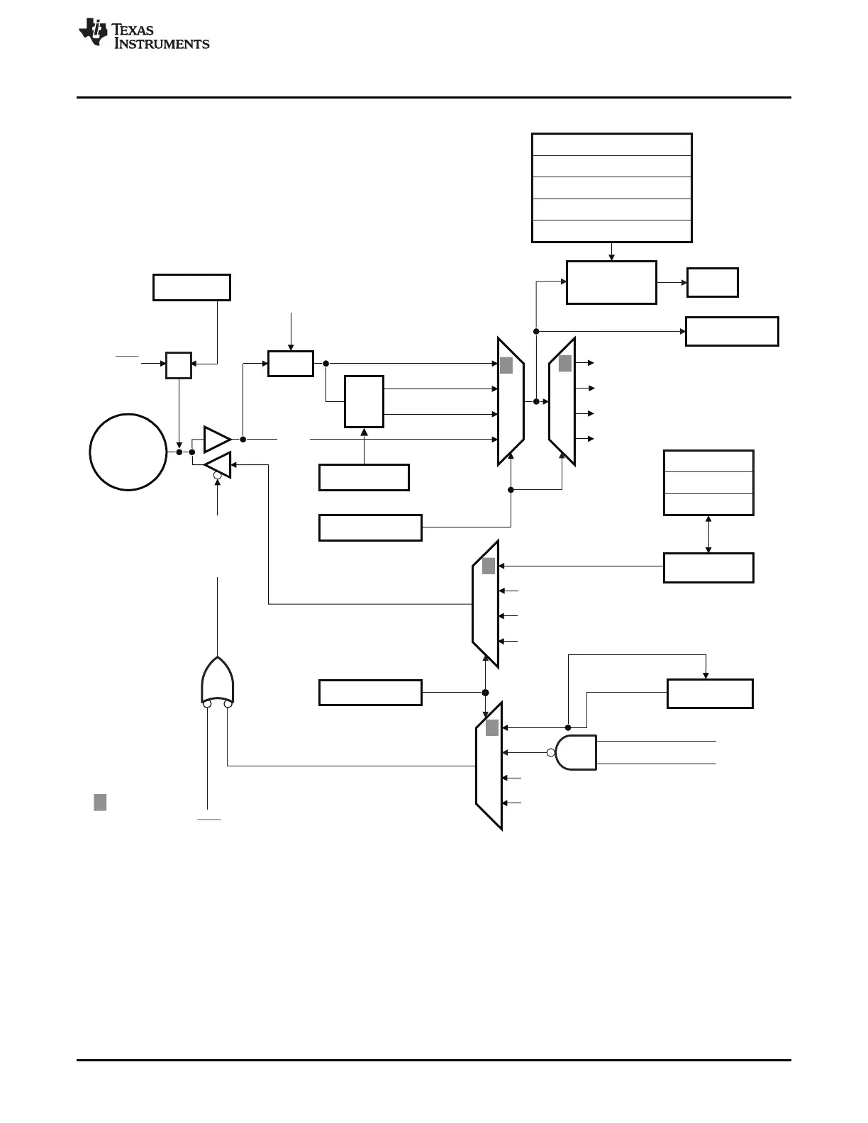
Figure 1-42. GPIO32, GPIO33 Multiplexing Diagram
A The GPIOINENCLK bit in the PCLKCR3 register does not affect the above GPIOs (I2C pins) since the pins are bi-
directional.
B The input qualification circuit is not reset when modes are changed (such as changing from output to input mode).
Any state will get flushed by the circuit eventually.
 Loading...