Receiver Configuration
www.ti.com
700
SPRUI07–March 2020
Submit Documentation Feedback
Copyright © 2020, Texas Instruments Incorporated
Multichannel Buffered Serial Port (McBSP)
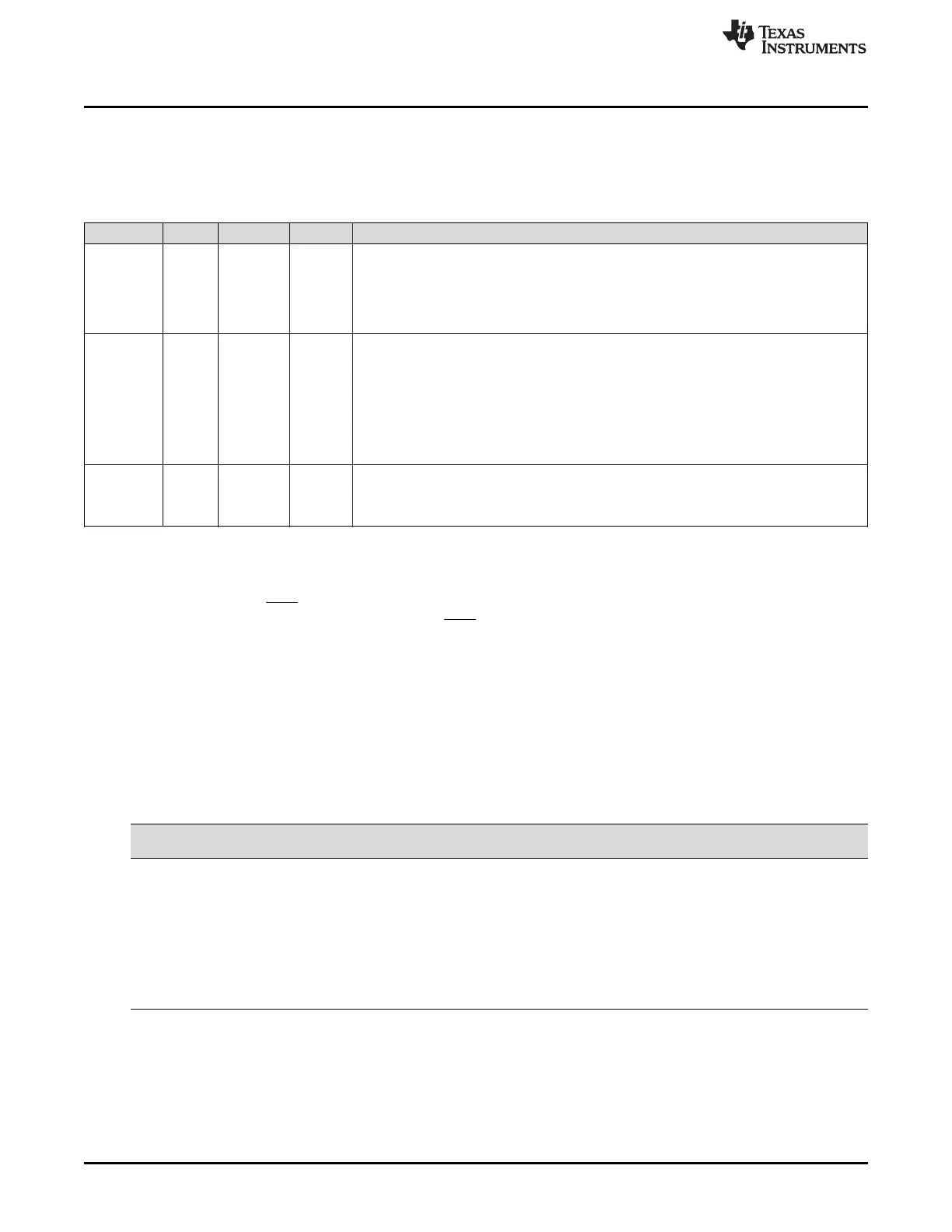
12.8.2 Resetting and Enabling the Receiver
The first step of the receiver configuration procedure is to reset the receiver, and the last step is to enable
the receiver (to take it out of reset). Table 12-18 describes the bits used for both of these steps.
Table 12-18. Register Bits Used to Reset or Enable the McBSP Receiver Field Descriptions
Register Bit Field Value Description
SPCR2 7 FRST Frame-synchronization logic reset
0 Frame-synchronization logic is reset. The sample rate generator does not generate frame-
synchronization signal FSG, even if GRST = 1.
1 If GRST = 1, frame-synchronization signal FSG is generated after (FPER + 1) number of
CLKG clock cycles; all frame counters are loaded with their programmed values.
SPCR2 6 GRST Sample rate generator reset
0 Sample rate generator is reset. If GRST = 0 due to a DSP reset, CLKG is driven by the
CPU clock divided by 2, and FSG is driven low (inactive). If GRST = 0 due to program
code, CLKG and FSG are both driven low (inactive).
1 Sample rate generator is enabled. CLKG is driven according to the configuration
programmed in the sample rate generator registers (SRGR[1,2]). If FRST = 1, the
generator also generates the frame-synchronization signal FSG as programmed in the
sample rate generator registers.
SPCR1 0 RRST Receiver reset
0 The serial port receiver is disabled and in the reset state.
1 The serial port receiver is enabled.
12.8.2.1 Reset Considerations
The serial port can be reset in the following two ways:
1. The DSP reset (XRS signal driven low) places the receiver, transmitter, and sample rate generator in
reset. When the device reset is removed (XRS signal released), GRST = FRST = RRST = XRST = 0
keep the entire serial port in the reset state, provided the McBSP clock is turned on.
2. The serial port transmitter and receiver can be reset directly using the RRST and XRST bits in the
serial port control registers. The sample rate generator can be reset directly using the GRST bit in
SPCR2.
Table 12-19 shows the state of McBSP pins when the serial port is reset due to a device reset and a
direct receiver/transmitter reset.
For more details about McBSP reset conditions and effects, see Section 12.10.2.
Table 12-19. Reset State of Each McBSP Pin
Pin
Possible
State(s)
State Forced By
Device Reset
State Forced By Receiver Reset
(RRST = 0 and GRST = 1)
MDRx I GPIO Input Input
MCLKRx I/O/Z GPIO Input Known state if input; MCLKR running if output
MFSRx I/O/Z GPIO Input Known state if input; FSRP inactive state if output
Transmitter reset (XRST = 0 and GRST = 1)
MDXx O/Z GPIO Input Low impedance after transmit bit clock provided
MCLKXx I/O/Z GPIO Input Known state if input; CLKX running if output
MFSXx I/O/Z GPIO Input Known state if input; FSXP inactive state if output
12.8.3 Set the Receiver Pins to Operate as McBSP Pins
To configure a pin for its McBSP function , you should configure the bits of the GPxMUXn register
appropriately. In addition to this, bits 12 and 13 of the PCR register must be set to 0. These bits are
defined as reserved.
 Loading...