WDCNTR
Overflow
1-count
delay
WDCR.WDDISWDCR.WDPSWDCR.WDPRECLKDIV
WDCLK
(INTOSC1)
WDCLK
Divider
Watchdog
Prescaler
8-bit
Watchdog
Counter
SCSR.WDOVERRIDE
Watchdog
Key Detector
55 + AA
WDKEY (7:0)
Generate
512-WDCLK
Output Pulse
Good Key
Bad Key
Out of Window
Watchdog
Window
Detector
WDWCR.MIN
Count
Watchdog Time-out
SYSRSn
Clear
SCSR.WDENINT
WDRSTn
WDINTn
WDCR(WDCHK(2:0))
1 0 1
Clocking and System Control
www.ti.com
76
SPRUI07–March 2020
Submit Documentation Feedback
Copyright © 2020, Texas Instruments Incorporated
System Control and Interrupts
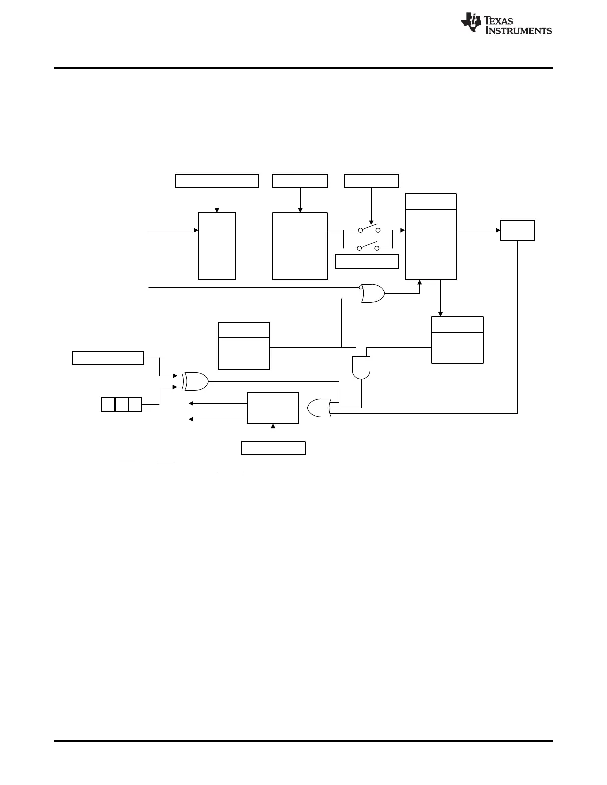
1.3.4 Watchdog Block
The watchdog module generates an output pulse, 512 oscillator-clocks (OSCCLK) wide whenever the 8-
bit watchdog up counter has reached its maximum value. To prevent this, the user can either disable the
counter or the software must periodically write a 0x55 + 0xAA sequence into the watchdog key register
which resets the watchdog counter. Figure 1-26 shows the various functional blocks within the watchdog
module.
Figure 1-26. Watchdog Module
A The WDRST and XRS signals are driven low for 512 OSCCLK cycles when a watchdog reset occurs. Likewise, if the
watchdog interrupt is enabled, the WDINT signal will be driven low for 512 OSCCLK cycles when an interrupt occurs.
Watchdog is not functional and cannot generate a reset when OSCCLK is not present.
 Loading...