McBSP Registers
www.ti.com
756
SPRUI07–March 2020
Submit Documentation Feedback
Copyright © 2020, Texas Instruments Incorporated
Multichannel Buffered Serial Port (McBSP)
XWDLEN2) and the number of words (XFRLEN1, XFRLEN2)
• Choose a transmit companding mode, if any (XCOMPAND)
• Enable or disable the transmit frame-sync ignore function (XFIG)
• Choose a transmit data delay (XDATDLY)
12.15.6.1 Transmit Control 1 Register (XCR1)
The transmit control 1 register (XCR1) is shown in Figure 12-73 and described in Table 12-83.
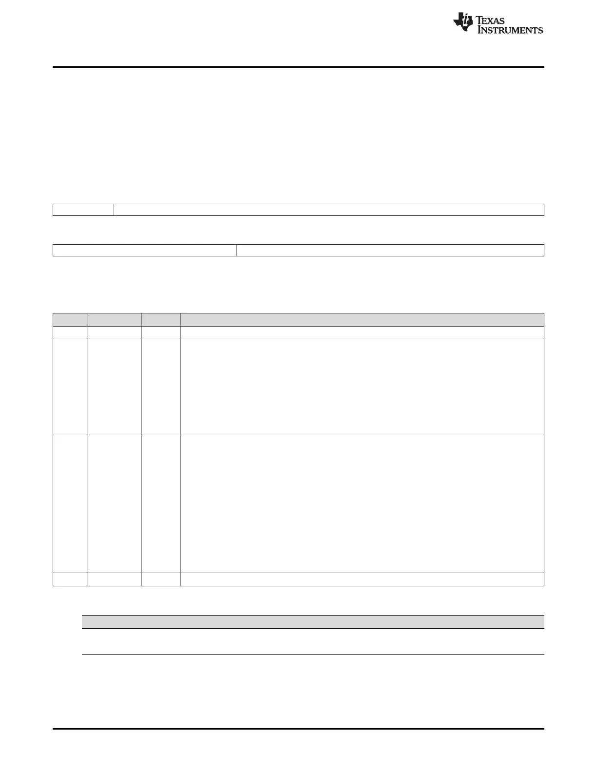
Figure 12-73. Transmit Control 1 Register (XCR1)
15 14 8
Reserved XFRLEN1
R-0 R/W-0
7 5 4 0
XWDLEN1 Reserved
R/W-0 R-0
LEGEND: R/W = Read/Write; R = Read only; -n = value after reset
Table 12-83. Transmit Control 1 Register (XCR1) Field Descriptions
Bit Field Value Description
15 Reserved 0 Reserved bit. Read-only; returns 0 when read.
14-8 XFRLEN1 0-7Fh Transmit frame length 1 (1 to 128 words). Each frame of transmit data can have one or two phases,
depending on value that you load into the XPHASE bit. If a single-phase frame is selected, XFRLEN1
in XCR1 selects the number of serial words (8, 12, 16, 20, 24, or 32 bits per word) in the frame. If a
dual-phase frame is selected, XFRLEN1 determines the number of serial words in phase 1 of the
frame and XFRLEN2 in XCR2 determines the number of words in phase 2 of the frame. The 7-bit
XFRLEN fields allow up to 128 words per phase. See Table 12-84 for a summary of how you
determine the frame length. This length corresponds to the number of words or logical time slots or
channels per frame-synchronization period.
Program the XFRLEN fields with [w minus 1], where w represents the number of words per phase. For
example, if you want a phase length of 128 words in phase 1, load 127 into XFRLEN1.
7-5 XWDLEN1 0-3h Transmit word length 1. Each frame of transmit data can have one or two phases, depending on the
value that you load into the XPHASE bit. If a single-phase frame is selected, XWDLEN1 in XCR1
selects the length for every serial word transmitted in the frame. If a dual-phase frame is selected,
XWDLEN1 determines the length of the serial words in phase 1 of the frame and XWDLEN2 in XCR2
determines the word length in phase 2 of the frame.
0 8 bits
1h 12 bits
2h 16 bits
3h 20 bits
4h 24 bits
5h 32 bits
6h-7h Reserved (do not use)
4-0 Reserved 0 Reserved bits. They are read-only bits and return 0s when read.
Table 12-84. Frame Length Formula for Transmit Control 1 Register (XCR1)
XPHASE XFRLEN1 XFRLEN2 Frame Length
0 0 ≤ XFRLEN1 ≤ 127 Not used (XFRLEN1 + 1) words
1 0 ≤ XFRLEN1 ≤ 127 0 ≤ XFRLEN2 ≤ 127 (XFRLEN1 + 1) + (XFRLEN2 + 1) words
12.15.6.2 Transmit Control 2 Register (XCR2)
The transmit control 2 register (XCR2) is shown in Figure 12-74 and described in Table 12-85.
 Loading...