DXR1 to XSR1 copy (W1)
XRDY
DXR1 to XSR1 copy (W3)
Write to DXR1(W3)
DX
RBR1 to DRR1 (W3)
Read From DRR1(W1)
RBR1 to DRR1 copy (W1)RBR1 to DRR1 copy (W3)
Read From DRR1(W3)
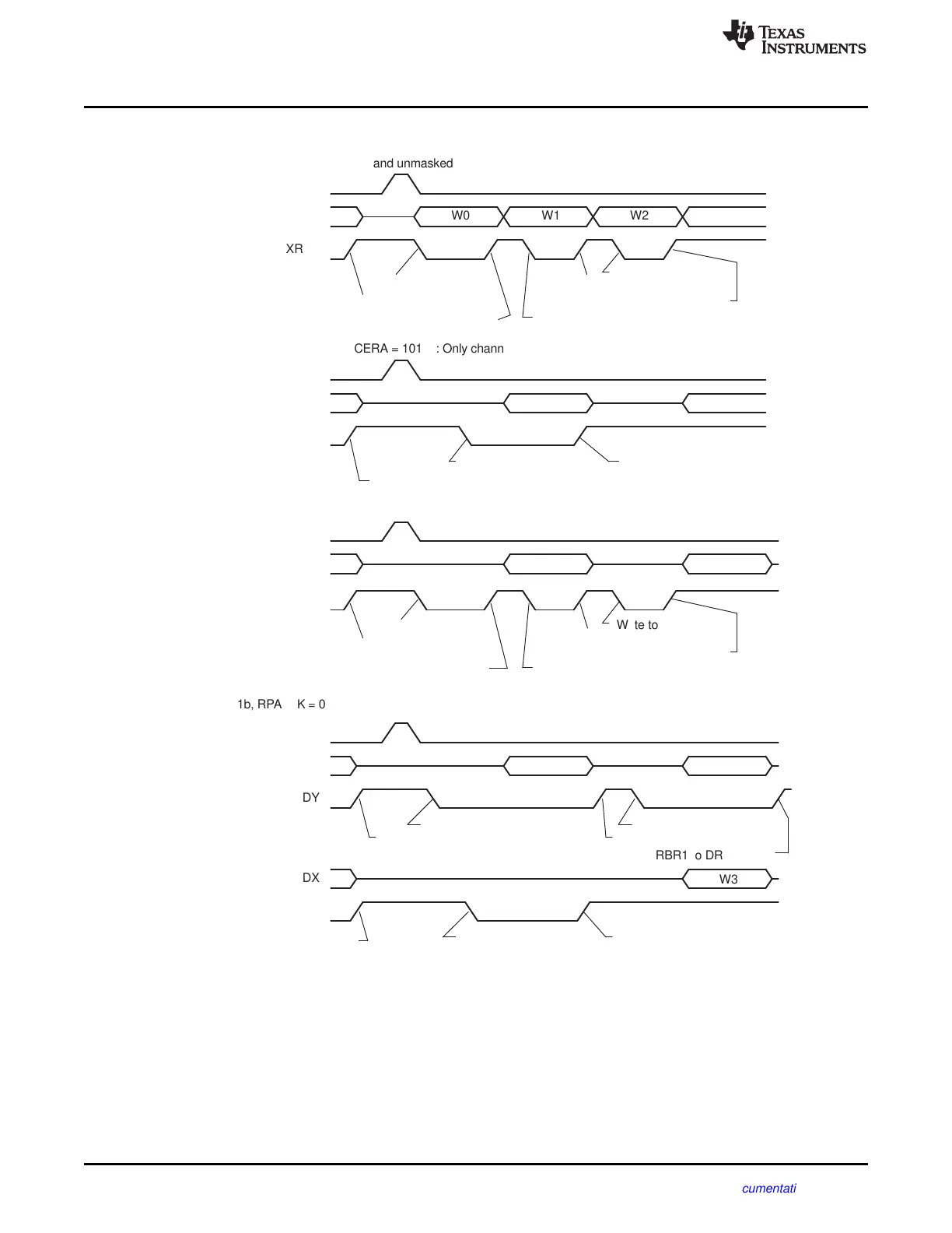
(d) XMCM = 11b, RPABLK = 00b, XPABLK = X, RCERA = 1010b, XCERA = 1000b:
Receive channels: 1 and 3 enabled; transmit channels: 1 and 3 enabled, but only 3 unmasked
Internal FS(R/X)
DR
RRDY
Write to DXR1(W3)
DXR1 to XSR1 copy(W0)
Write to DXR1(W1)
DXR1 to XSR1 copy(W1)
Write to DXR1(W2)
XRDY
DXR1 to XSR1 copy(W3)
DXR1 to XSR1 copy(W2)
W3
(c) XMCM = 10b, XPABLK = 00b, XCERA = 1010b: All channels enabled, only 1 and 3 unmasked
Internal FSX
DX
(b) XMCM = 01b, XPABLK = 00b, XCERA = 1010b: Only channels 1 and 3 enabled and unmasked
DXR1 to XSR1 copy(W3)Write to DXR1(W3)
XRDY
DXR1 to XSR1 copy(W1)
W3
W1
Internal FSX
(a) XMCM = 00b: All channels enabled and unmasked
W3W2W1W0
XRDY
DX
Internal FSX
DXR1 to XSR1 copy(W0)
Write to DXR1(W1)
DXR1 to XSR1 copy(W1)
Write to DXR1(W2)
DXR1 to XSR1 copy(W3)
DXR1 to XSR1 copy(W2)
Write to DXR1(W3)
SPI Operation Using the Clock Stop Mode
www.ti.com
692
SPRUI07–March 2020
Submit Documentation Feedback
Copyright © 2020, Texas Instruments Incorporated
Multichannel Buffered Serial Port (McBSP)
Figure 12-35. Activity on McBSP Pins for the Possible Values of XMCM
12.7 SPI Operation Using the Clock Stop Mode
This chapter explains how to use the McBSP in SPI mode.
12.7.1 SPI Protocol
The SPI protocol is a master-slave configuration with one master device and one or more slave devices.
The interface consists of the following four signals:
• Serial data input (also referred to as master in/slave out, or SPISOMI)
 Loading...