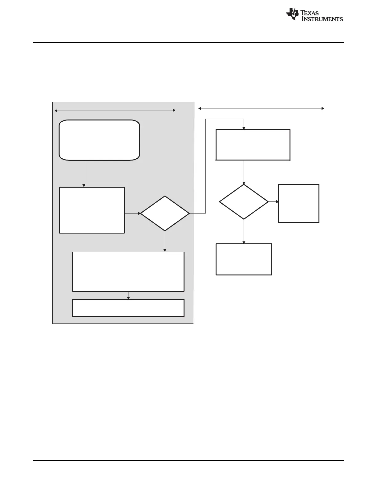
Reset
(power-on reset or warm reset)
Reset vector fetched from
boot ROM
Branch into bootloader
routines, depending on the
state of GPIO pins
Yes
Using
peripheral
interrupts
?
PIE disabled (ENPIE=0)
OBJMODE = 0
AMODE = 0
Yes
User code initializes:
OBJMODE and AMODE state
†
PIE enable (ENPIE = 1)
CPU IER register and INTM
Vectors (except for reset)
are fetched from PIE vector map
‡
Recommended flow for 280x applications
No
User code initializes:
OBJMODE and AMODE state1
CPU IER register and INTM
VMAP state
VMAP = 1
?
Vectors
(except for reset)
are fetched
from M0 vector
map
‡
Vectors
Used for test purposes only
No
PIE vector table
PIEIERx registers
VMAP = 1
MOM1MAP = 1
(except for reset) are
fetched from BROM
vector map
‡
Peripheral Interrupt Expansion (PIE)
www.ti.com
142
SPRUI07–March 2020
Submit Documentation Feedback
Copyright © 2020, Texas Instruments Incorporated
System Control and Interrupts
After the reset and boot is complete, the PIE vector table should be initialized by the user's code. Then the
application enables the PIE vector table. From that point on the interrupt vectors are fetched from the PIE
vector table. Note: when a reset occurs, the reset vector is always fetched from BROM as shown in
Table 1-110. After a reset the PIE vector table is always disabled.
Figure 1-80 illustrates the process by which the vector table mapping is selected.
Figure 1-80. Reset Flow Diagram
A The compatibility operating mode of the 28x CPU is determined by a combination of the OBJMODE and AMODE bits
in Status Register 1 (ST1):
Operating Mode OBJMODE AMODE
C28x Mode 1 0
24x/240x Source-Compatible 1 1
C27x Object-Compatible 0 0 (Default at reset)
B The reset vector is always fetched from the boot ROM.
 Loading...