+1 +1 +1+1 +1+1+1 −1 −1 −1−1 −1−1−1−1 −1−1 −1 +1+1+1
−1 −1 −1 −1 −1 −1 −1 +1 +1 +1 +1 +1 +1 +1+1+1+1 +1 −1−1−1
QA
QB
QCLK
QDIR
QPOSCNT
QA
QB
QCLK
QDIR
QPOSCNT
www.ti.com
Quadrature Decoder Unit (QDU)
397
SPRUI07–March 2020
Submit Documentation Feedback
Copyright © 2020, Texas Instruments Incorporated
Enhanced Quadrature Encoder Pulse (eQEP)
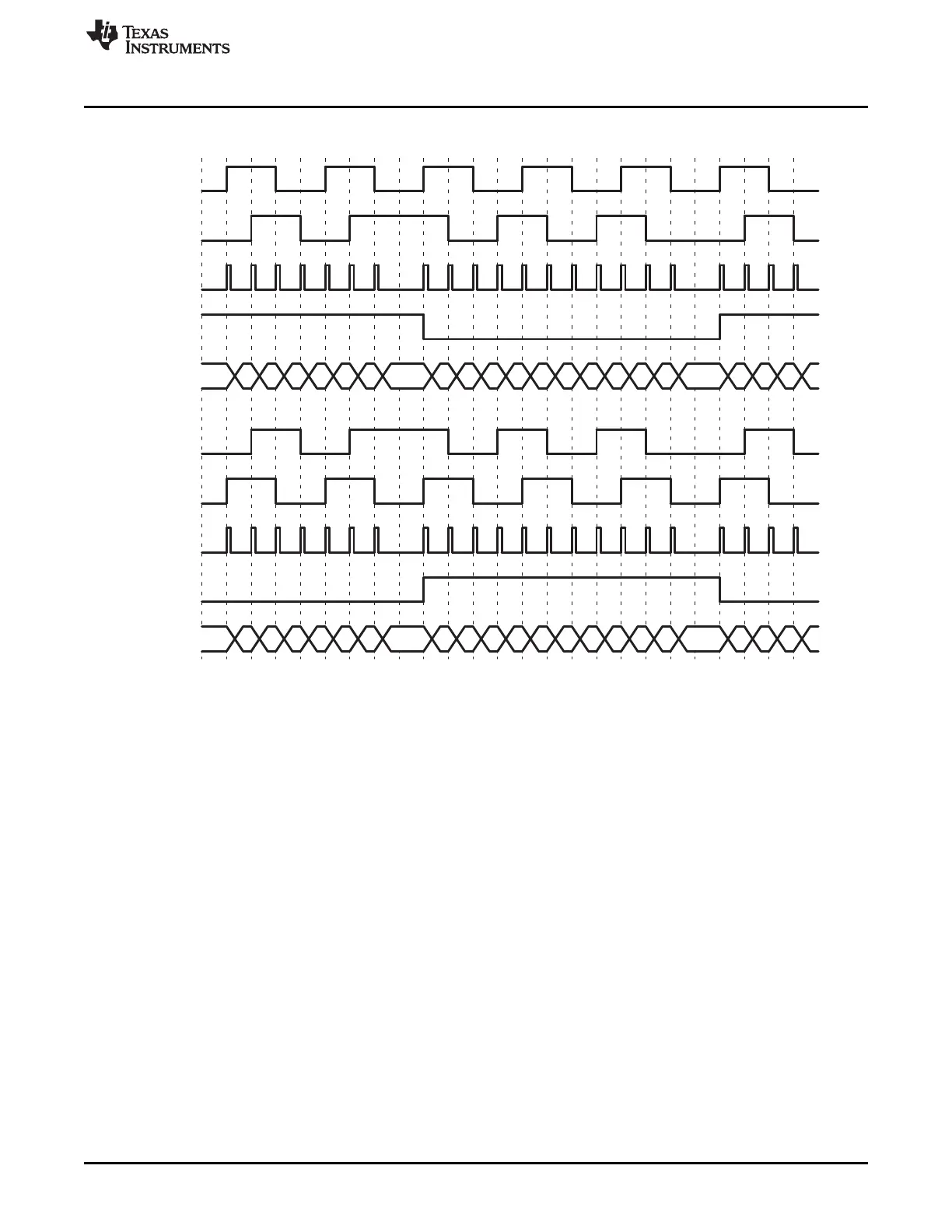
Figure 6-7. Quadrature-clock and Direction Decoding
Phase Error Flag— In normal operating conditions, quadrature inputs QEPA and QEPB will be 90
degrees out of phase. The phase error flag (PHE) is set in the QFLG register and the QPOSCNT
value can be incorrect and offset by multiples of 1 or 3. That is, when edge transition is detected
simultaneously on the QEPA and QEPB signals to optionally generate interrupts. State transitions
marked by dashed lines in Figure 6-6 are invalid transitions that generate a phase error.
Count Multiplication— The eQEP position counter provides 4x times the resolution of an input clock by
generating a quadrature-clock (QCLK) on the rising/falling edges of both eQEP input clocks (QEPA
and QEPB) as shown in Figure 6-7 .
Reverse Count— In normal quadrature count operation, QEPA input is fed to the QA input of the
quadrature decoder and the QEPB input is fed to the QB input of the quadrature decoder. Reverse
counting is enabled by setting the SWAP bit in the QDECCTL register. This will swap the input to
the quadrature decoder, thereby reversing the counting direction.
6.4.1.2 Direction-Count Mode
Some position encoders provide direction and clock outputs, instead of quadrature outputs. In such cases,
direction-count mode can be used. QEPA input will provide the clock for the position counter and the
QEPB input will have the direction information. The position counter is incremented on every rising edge
of a QEPA input when the direction input is high, and decremented when the direction input is low.
 Loading...