Address Data Last Data
First frame within block
Is address; it follows idle
period of 10 bits or more
Frame within
block
Idle period
less than 10
bits
Idle period
of 10 bits
or more
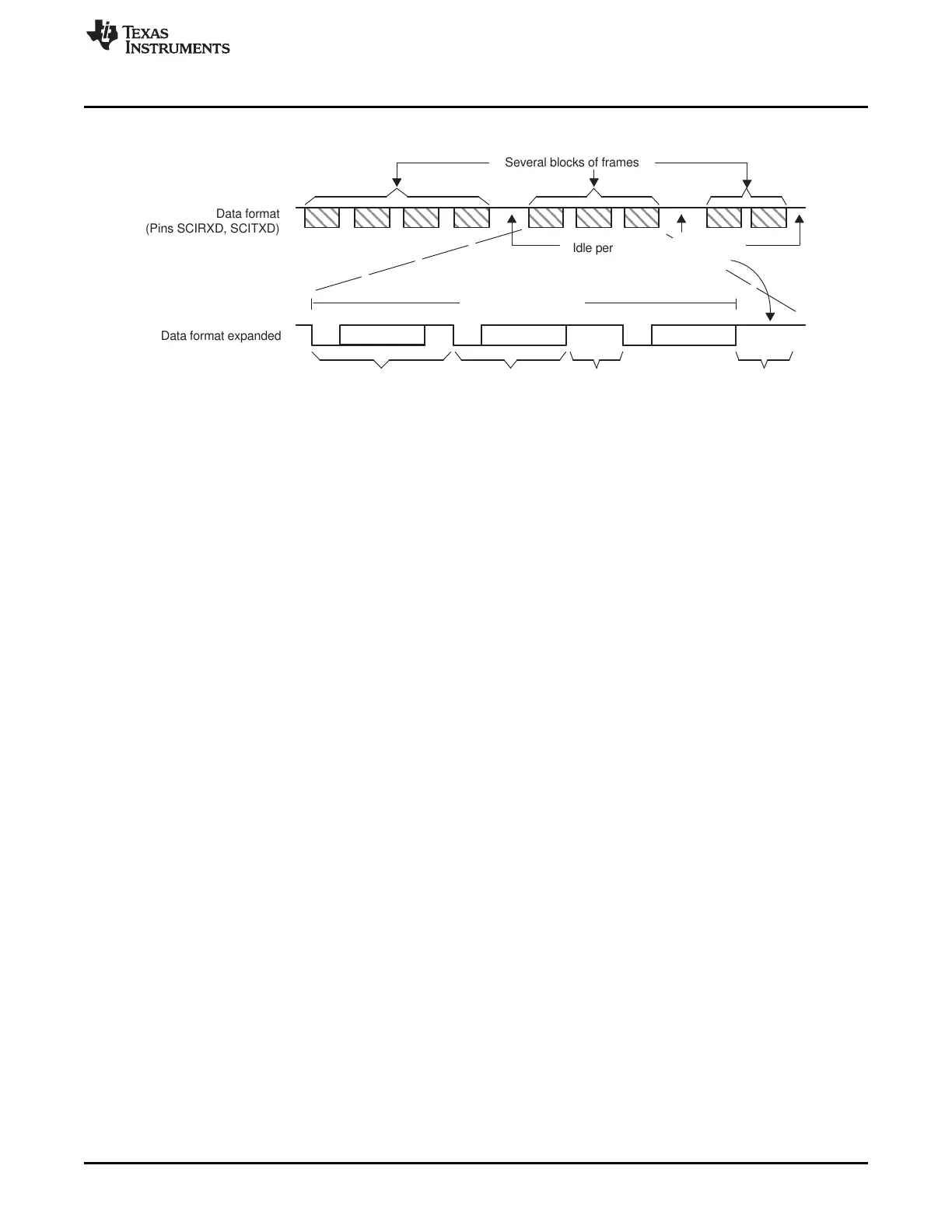
Several blocks of frames
Data format
(Pins SCIRXD, SCITXD)
Data format expanded
Idle periods of 10 bits or more
separate the blocks
Start
Start
Start
One block of frames
www.ti.com
Idle-Line Multiprocessor Mode
587
SPRUI07–March 2020
Submit Documentation Feedback
Copyright © 2020, Texas Instruments Incorporated
Serial Communications Interface (SCI)
Figure 10-4. Idle-Line Multiprocessor Communication Format
10.8.1 Idle-Line Mode Steps
The steps followed by the idle-line mode:
Step 1. SCI wakes up after receipt of the block-start signal.
Step 2. The processor recognizes the next SCI interrupt.
Step 3. The interrupt service routine compares the received address (sent by a remote transmitter) to
its own.
Step 4. If the CPU is being addressed, the service routine clears the SLEEP bit and receives the rest
of the data block.
Step 5. If the CPU is not being addressed, the SLEEP bit remains set. This lets the CPU continue to
execute its main program without being interrupted by the SCI port until the next detection of
a block start.
 Loading...