QWDTMR
QWDPRD
16
QWDOG
UTIME
QUPRD
QUTMR
32
UTOUT
WDTOUT
Quadrature
capture unit
(QCAP)
QCPRDLAT
QCTMRLAT
16
QFLG
QEPSTS
QEPCTL
Registers
used by
multiple units
QCLK
QDIR
QI
QS
PHE
PCSOUT
Quadrature
decoder
(QDU)
QDECCTL
16
Position counter/
control unit
(PCCU)
QPOSLAT
QPOSSLAT
32
QPOSILAT
EQEPxAIN
EQEPxBIN
EQEPxIIN
EQEPxIOUT
EQEPxIOE
EQEPxSIN
EQEPxSOUT
EQEPxSOE
GPIO
MUX
EQEPxA/XCLK
EQEPxB/XDIR
EQEPxS
EQEPxI
QPOSCMP
QEINT
QFRC
32
QCLR
QPOSCTL
1632
QPOSCNT
QPOSMAX
QPOSINIT
PIE
EQEPxINT
Enhanced QEP (eQEP) peripheral
System
control registers
QCTMR
QCPRD
1616
QCAPCTL
EQEPxENCLK
SYSCLKOUT
Data bus
To CPU
www.ti.com
Description
393
SPRUI07–March 2020
Submit Documentation Feedback
Copyright © 2020, Texas Instruments Incorporated
Enhanced Quadrature Encoder Pulse (eQEP)
The eQEP encoder uses an index signal to assign an absolute start position from which position
information is incrementally encoded using quadrature pulses. This pin is connected to the index
output of the eQEP encoder to optionally reset the position counter for each revolution. This signal can
be used to initialize or latch the position counter on the occurrence of a desired event on the index pin.
• QEPS: Strobe Input
This general-purpose strobe signal can initialize or latch the position counter on the occurrence of a
desired event on the strobe pin. This signal is typically connected to a sensor or limit switch to notify
that the motor has reached a defined position.
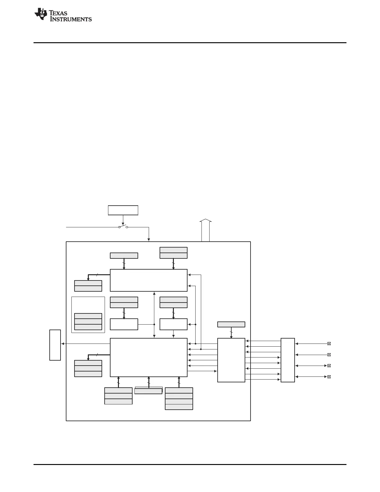
6.3.2 Functional Description
The eQEP peripheral contains the following major functional units (as shown in Figure 6-4):
• Programmable input qualification for each pin (part of the GPIO MUX)
• Quadrature decoder unit (QDU)
• Position counter and control unit for position measurement (PCCU)
• Quadrature edge-capture unit for low-speed measurement (QCAP)
• Unit time base for speed/frequency measurement (UTIME)
• Watchdog timer for detecting stalls (QWDOG)
Figure 6-4. Functional Block Diagram of the eQEP Peripheral
 Loading...