SPI Registers
www.ti.com
574
SPRUI07–March 2020
Submit Documentation Feedback
Copyright © 2020, Texas Instruments Incorporated
Serial Peripheral Interface (SPI)
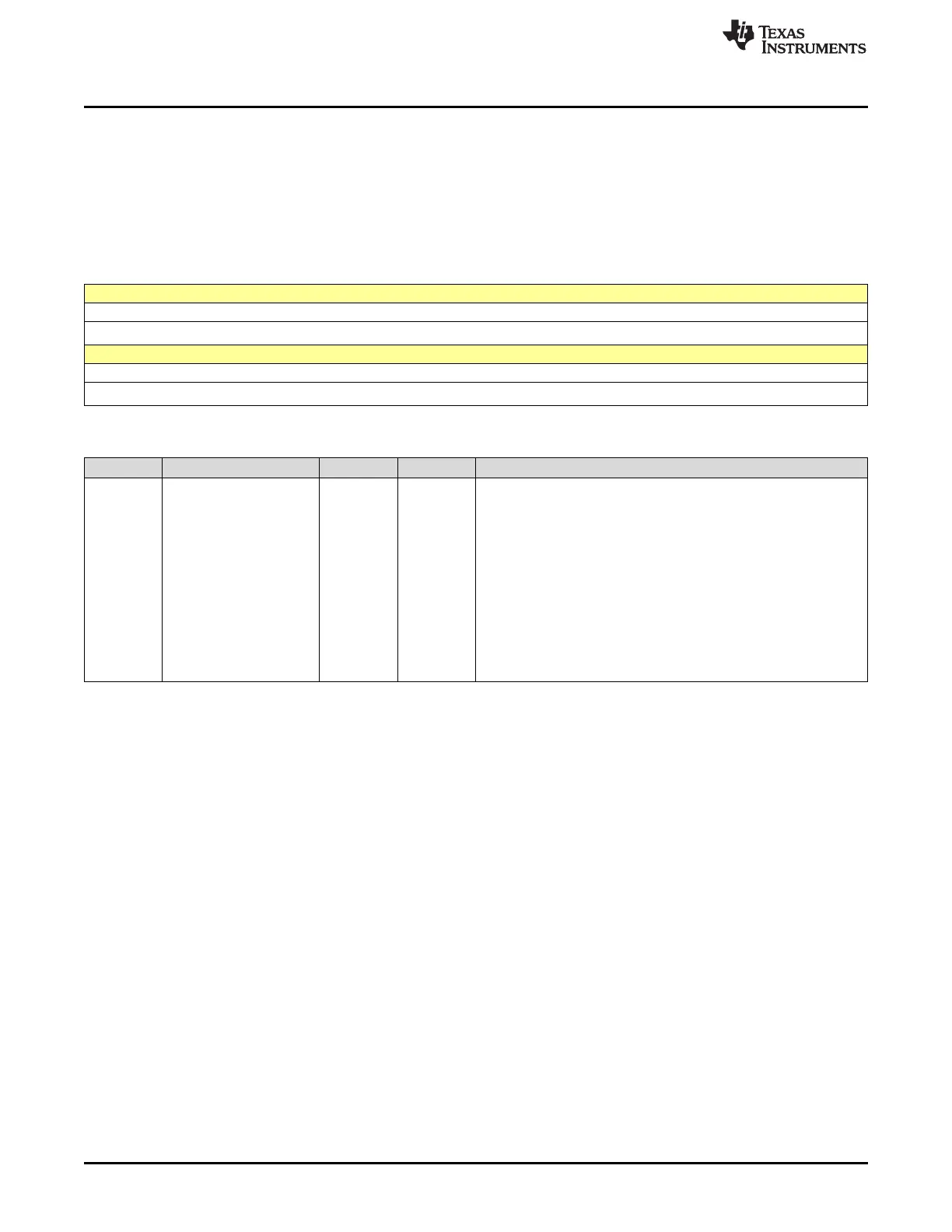
9.5.2.8 SPIDAT Register (Offset = 9h) [reset = 0h]
SPIDAT is shown in Figure 9-15 and described in Table 9-14.
Return to the Summary Table.
SPIDAT is the transmit and receive shift register. Data written to SPIDAT is shifted out (MSB) on
subsequent SPICLK cycles. For every bit (MSB) shifted out of the SPI, a bit is shifted into the LSB end of
the shift register.
Figure 9-15. SPIDAT Register
15 14 13 12 11 10 9 8
SDATn
R/W-0h
7 6 5 4 3 2 1 0
SDATn
R/W-0h
Table 9-14. SPIDAT Register Field Descriptions
Bit Field Type Reset Description
15-0 SDATn R/W 0h
Serial Data Shift Register
- It provides data to be output on the serial output pin if the TALK bit
(SPICTL.1) is set.
- When the SPI is operating as a master, a data transfer is initiated.
When initiating a transfer, check the CLOCK POLARITY bit
(SPICCR.6) described in Section 10.2.1.1 and the CLOCK PHASE
bit (SPICTL.3) described in Section 10.2.1.2, for the requirements.
In master mode, writing dummy data to SPIDAT initiates a receiver
sequence. Since the data is not hardware-justified for characters
shorter than sixteen bits, transmit data must be written in left-justified
form, and received data read in right-justified form.
Reset type: SYSRSn
 Loading...