T
0
0 1 2 3 4 5 6 7 N−6 N−5 N−4 N−3 N−2 N−1
0
QEPA
QEPB
QEPI
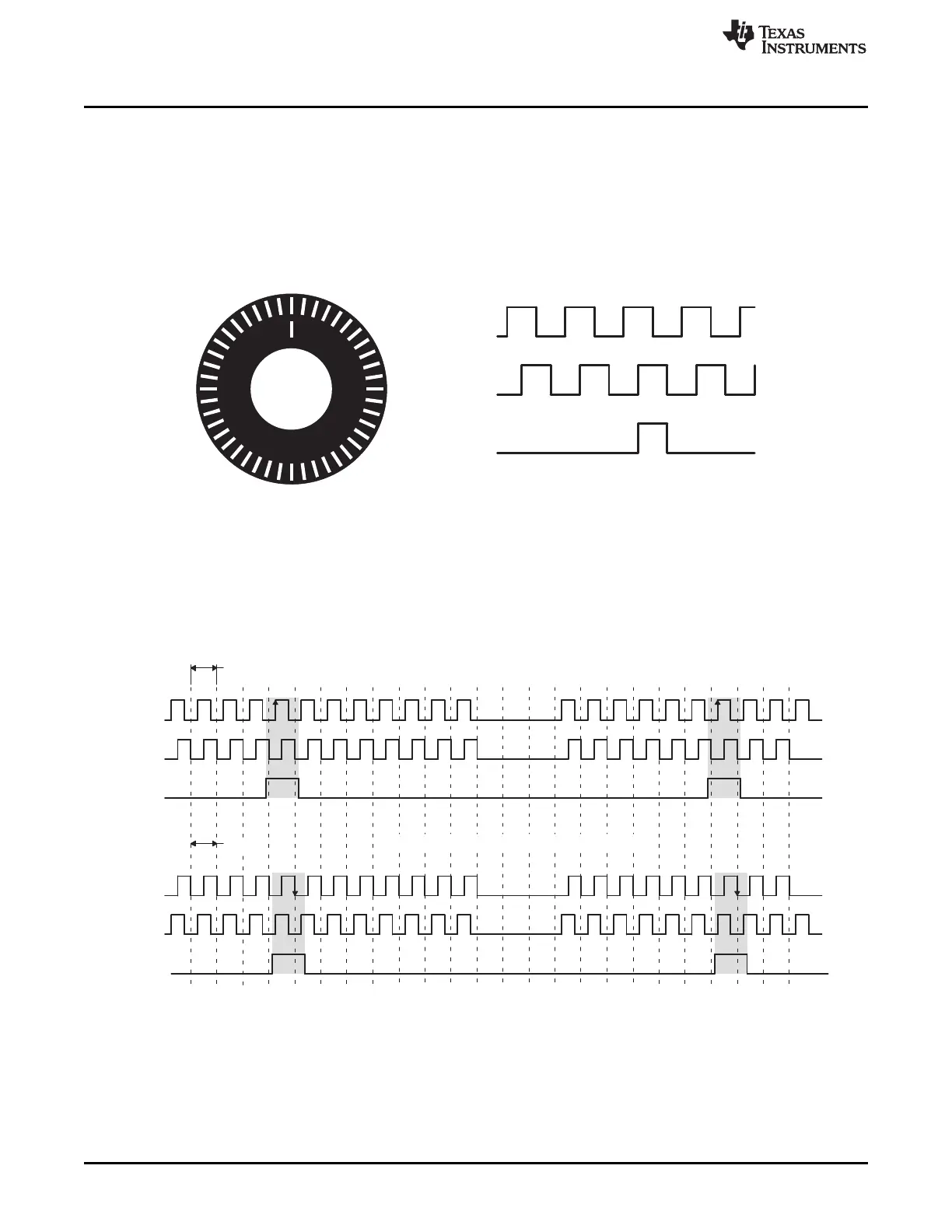
Clockwise shaft rotation/forward movement
Anti-clockwise shaft rotation/reverse movement
0 N−1 N−2 N−3 N−4 N−5 N−6 N−7 6 5 4 3 2 1 0 N−1 N−2
QEPA
QEPB
QEPI
T
0
Legend: N = lines per revolution
Introduction
www.ti.com
390
SPRUI07–March 2020
Submit Documentation Feedback
Copyright © 2020, Texas Instruments Incorporated
Enhanced Quadrature Encoder Pulse (eQEP)
6.1 Introduction
An incremental encoder disk is patterned with a track of slots along its periphery, as shown in Figure 6-1.
These slots create an alternating pattern of dark and light lines. The disk count is defined as the number
of dark and light line pairs that occur per revolution (lines per revolution). As a rule, a second track is
added to generate a signal that occurs once per revolution (index signal: QEPI), which can be used to
indicate an absolute position. Encoder manufacturers identify the index pulse using different terms such as
index, marker, home position, and zero reference
Figure 6-1. Optical Encoder Disk
To derive direction information, the lines on the disk are read out by two different photo-elements that
"look" at the disk pattern with a mechanical shift of 1/4 the pitch of a line pair between them. This shift is
detected with a reticle or mask that restricts the view of the photo-element to the desired part of the disk
lines. As the disk rotates, the two photo-elements generate signals that are shifted 90° out of phase from
each other. These are commonly called the quadrature QEPA and QEPB signals. The clockwise direction
for most encoders is defined as the QEPA channel going positive before the QEPB channel and vise
versa as shown in Figure 6-2.
Figure 6-2. QEP Encoder Output Signal for Forward/Reverse Movement
The encoder wheel typically makes one revolution for every revolution of the motor, or the wheel may be
at a geared rotation ratio with respect to the motor. Therefore, the frequency of the digital signal coming
from the QEPA and QEPB outputs varies proportionally with the velocity of the motor. For example, a
2000-line encoder directly coupled to a motor running at 5000 revolutions per minute (rpm) results in a
frequency of 166.6 KHz, so by measuring the frequency of either the QEPA or QEPB output, the
processor can determine the velocity of the motor.
 Loading...