www.ti.com
SPI Registers
565
SPRUI07–March 2020
Submit Documentation Feedback
Copyright © 2020, Texas Instruments Incorporated
Serial Peripheral Interface (SPI)
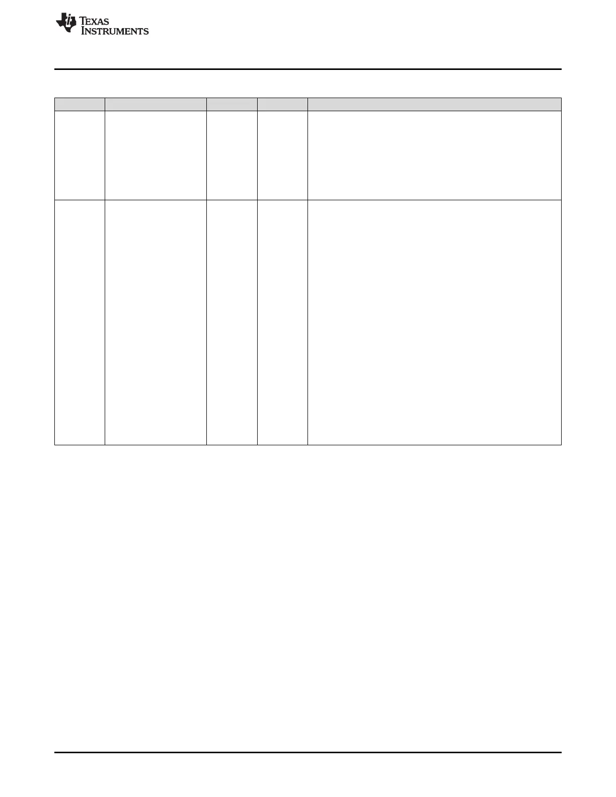
Table 9-7. SPICCR Register Field Descriptions (continued)
Bit Field Type Reset Description
4 SPILBK R/W 0h
SPI Loopback Mode Select
Loopback mode allows module validation during device testing. This
mode is valid only in master mode of the SPI.
Reset type: SYSRSn
0h (R/W) = SPI loopback mode disabled. This is the default value
after reset.
1h (R/W) = SPI loopback mode enabled, SIMO/SOMI lines are
connected internally. Used for module self-tests.
3-0 SPICHAR R/W 0h
Character Length Control Bits
These four bits determine the number of bits to be shifted in or SPI
CHAR0 out as a single character during one shift sequence.
SPICHAR = Word length - 1
Reset type: SYSRSn
0h (R/W) = 1-bit word
1h (R/W) = 2-bit word
2h (R/W) = 3-bit word
3h (R/W) = 4-bit word
4h (R/W) = 5-bit word
5h (R/W) = 6-bit word
6h (R/W) = 7-bit word
7h (R/W) = 8-bit word
8h (R/W) = 9-bit word
9h (R/W) = 10-bit word
Ah (R/W) = 11-bit word
Bh (R/W) = 12-bit word
Ch (R/W) = 13-bit word
Dh (R/W) = 14-bit word
Eh (R/W) = 15-bit word
Fh (R/W) = 16-bit word
 Loading...