SPI Baud Rate
LSPCLK
(SPIBRR 1)
=
+
www.ti.com
SPI Operation
557
SPRUI07–March 2020
Submit Documentation Feedback
Copyright © 2020, Texas Instruments Incorporated
Serial Peripheral Interface (SPI)
9.3.5 Baud Rate Selection
The SPI module supports 125 different baud rates and four different clock schemes. Depending on
whether the SPI clock is in slave or master mode, the SPICLK pin can receive an external SPI clock signal
or provide the SPI clock signal, respectively.
• In the slave mode, the SPI clock is received on the SPICLK pin from the external source, and can be
no greater than the LSPCLK frequency divided by 4.
• In the master mode, the SPI clock is generated by the SPI and is output on the SPICLK pin, and can
be no greater than the LSPCLK frequency divided by 4.
NOTE: The baud rate should be configured to not exceed the maximum rated GPIO toggle
frequency. Refer to the device Data Manual for the maximum GPIO toggle frequency
Example 9-2 shows how to determine the SPI baud rates.
Example 9-2. Baud Rate Determination
For SPIBRR = 3 to 127:
(8)
For SPIBRR = 0, 1, or 2:
(9)
where:
LSPCLK = Low-speed peripheral clock frequency of the device
SPIBRR = Contents of the SPIBRR in the master SPI device
To determine what value to load into SPIBRR, you must know the device system clock (LSPCLK) frequency
(which is device-specific) and the baud rate at which you will be operating.
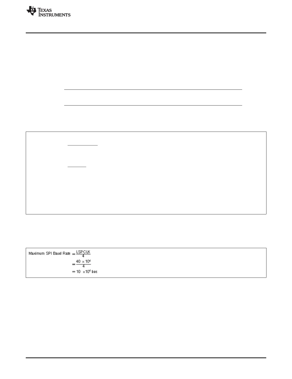
Example 9-3 shows how to calculate the baud rate of the SPI module.
Example 9-3. Baud Rate Calculation
(10)
 Loading...