www.ti.com
I2C Registers
649
SPRUI07–March 2020
Submit Documentation Feedback
Copyright © 2020, Texas Instruments Incorporated
Inter-Integrated Circuit Module (I2C)
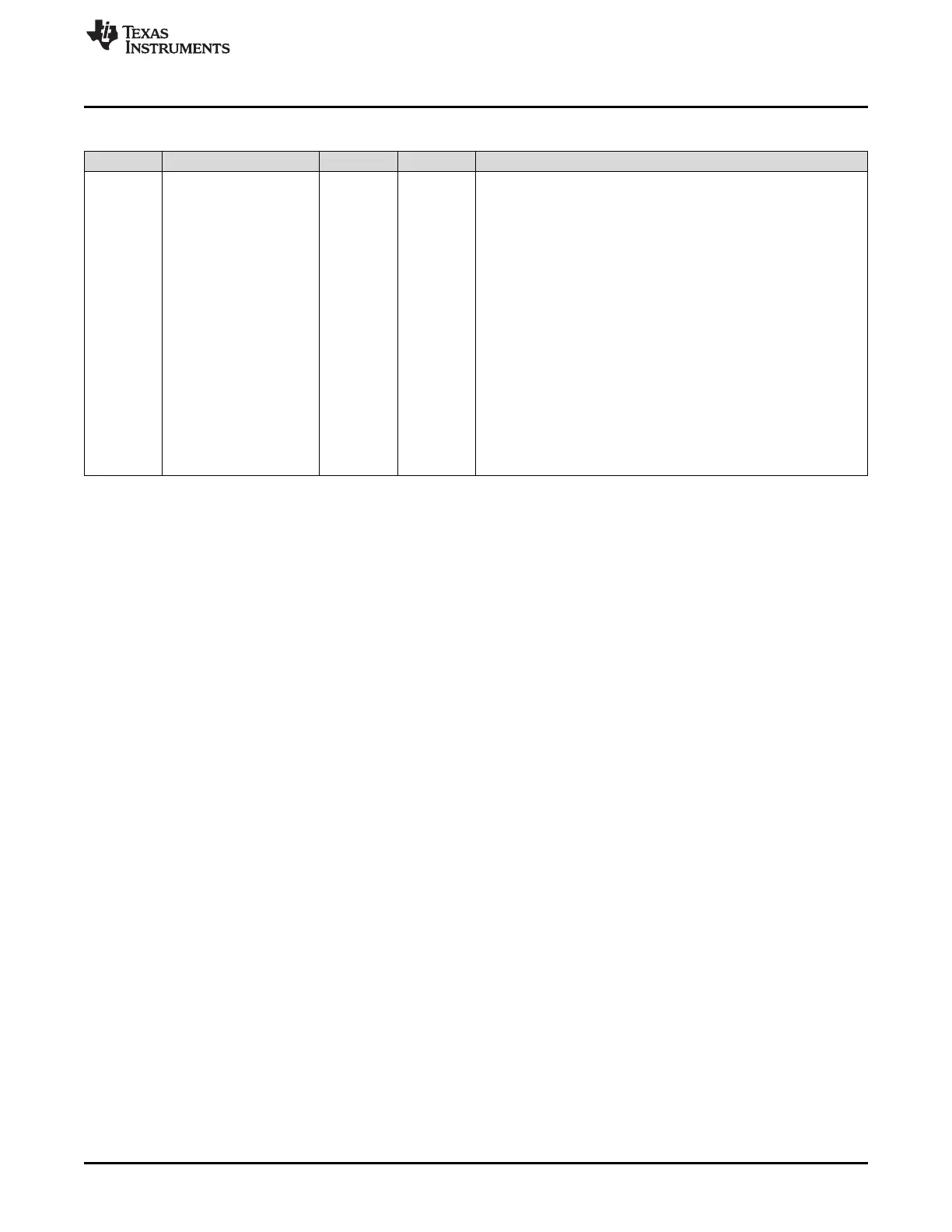
Table 11-19. I2CMDR Register Field Descriptions (continued)
Bit Field Type Reset Description
2-0 BC R/W 0h
Bit count bits.
BC defines the number of bits (1 to 8) in the next data byte that is to
be received or transmitted by the I2C module. The number of bits
selected with BC must match the data size of the other device.
Notice that when BC = 000b, a data byte has 8 bits. BC does not
affect address bytes, which always have 8 bits.
Note: If the bit count is less than 8, receive data is right-justified in
I2CDRR(7-0), and the other bits of I2CDRR(7-0) are undefined. Also,
transmit data written to I2CDXR must be right-justified
Reset type: SYSRSn
0h (R/W) = 8 bits per data byte
1h (R/W) = 1 bit per data byte
2h (R/W) = 2 bits per data byte
3h (R/W) = 3 bits per data byte
4h (R/W) = 4 bits per data byte
5h (R/W) = 5 bits per data byte
6h (R/W) = 6 bits per data byte
7h (R/W) = 7 bits per data byte
 Loading...