I2C Registers
www.ti.com
648
SPRUI07–March 2020
Submit Documentation Feedback
Copyright © 2020, Texas Instruments Incorporated
Inter-Integrated Circuit Module (I2C)
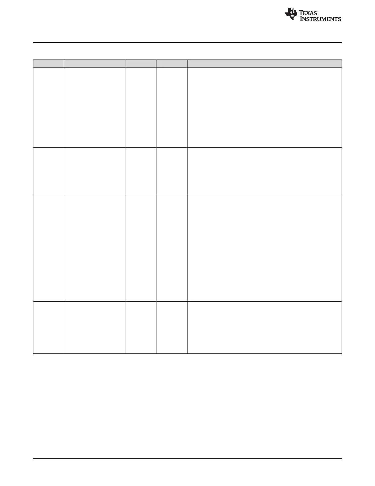
Table 11-19. I2CMDR Register Field Descriptions (continued)
Bit Field Type Reset Description
6 DLB R/W 0h
Digital loopback mode bit.
Reset type: SYSRSn
0h (R/W) = Digital loopback mode is disabled.
1h (R/W) = Digital loopback mode is enabled. For proper operation
in this mode, the MST bit must be 1.
In the digital loopback mode, data transmitted out of I2CDXR is
received in I2CDRR after n device cycles by an internal path,
where:
n = ((I2C input clock frequency/module clock frequency) x 8)
The transmit clock is also the receive clock. The address
transmitted on the SDA pin is the address in I2COAR.
Note: The free data format (FDF = 1) is not supported in the digital
loopback mode.
5 IRS R/W 0h
I2C module reset bit.
Reset type: SYSRSn
0h (R/W) = The I2C module is in reset/disabled. When this bit is
cleared to 0, all status bits (in I2CSTR) are set to their default
values.
1h (R/W) = The I2C module is enabled. This has the effect of
releasing the I2C bus if the I2C peripheral is holding it.
4 STB R/W 0h
START byte mode bit. This bit is only applicable when the I2C
module is a master. As described in version 2.1 of the Philips
Semiconductors I2C-bus specification, the START byte can be used
to help a slave that needs extra time to detect a START condition.
When the I2C module is a slave, it ignores a START byte from a
master, regardless of the value of the STB bit.
Reset type: SYSRSn
0h (R/W) = The I2C module is not in the START byte mode.
1h (R/W) = The I2C module is in the START byte mode. When you
set the START condition bit (STT), the I2C module begins the
transfer with more than just a START condition. Specifically, it
generates:
1. A START condition
2. A START byte (0000 0001b)
3. A dummy acknowledge clock pulse
4. A repeated START condition
Then, as normal, the I2C module sends the slave address that is in
I2CSAR.
3 FDF R/W 0h
Free data format mode bit.
Reset type: SYSRSn
0h (R/W) = Free data format mode is disabled. Transfers use the
7-/10-bit addressing format selected by the XA bit.
1h (R/W) = Free data format mode is enabled. Transfers have the
free data (no address) format described in Section 9.2.5.
The free data format is not supported in the digital loopback mode
(DLB=1).
 Loading...