Cortex-M3 Processor (Reference Material)
UG0331 User Guide Revision 15.0 98
A bit reads as one if the status of the corresponding interrupt is active or active and pending.
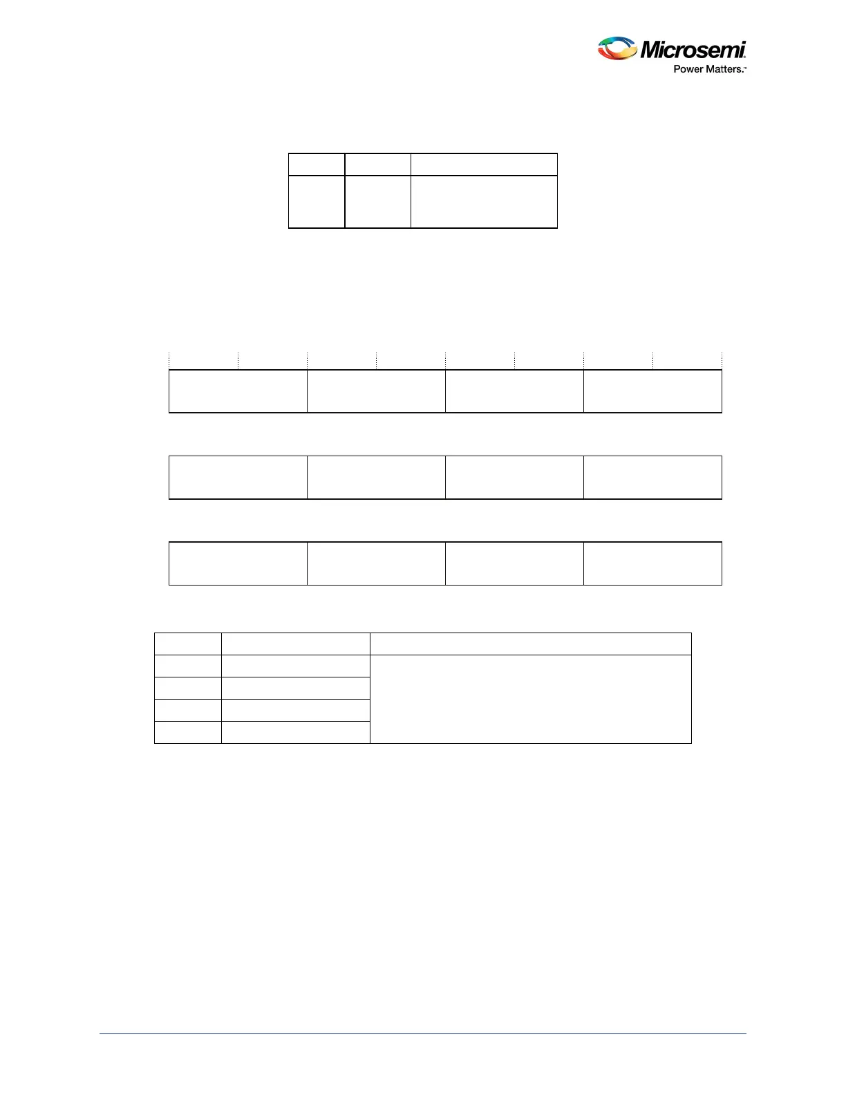
3.7.1.8 Interrupt Priority Registers
The NVIC_IPR0-NVIC_IPR59 registers provide an 8-bit priority field for each interrupt. These registers are byte-
accessible. See the register summary in Table 40, page 95 for their attributes. Each register holds four priority fields as
shown:
Figure 28 • IPR Register Bit Assignments
See Accessing the Cortex-M3 Processor NVIC Registers Using CMSIS, page 96 for more information
about the access to the interrupt priority array, which provides the software view of the interrupt priorities.
Find the IPR number and byte offset for interrupt m as follows:
• the corresponding IPRn number (see the preceding table), n is given by n = m DIV 4
• the byte offset of the required Priority field in this register is m MOD 4, where:
• byte offset 0 refers to register bits [7:0]
• byte offset 1 refers to register bits [15:8]
• byte offset 2 refers to register bits [23:16]
• byte offset 3 refers to register bits [31:24].
Table 46 • NVIC_IABR Bit Assignments
Bits Name Function
[31:0] ACTIVE Interrupt active flags:
0: interrupt not active
1: interrupt active.
Table 47 • NVIC_IPR Bit Assignments
Bits Name Function
[31:24] Priority, byte offset 3 Each priority field holds a priority value, 0-255. The lower
the value, the greater the priority of the corresponding
interrupt. The processor implements only bits [7:n] of
each field, bits [n-1:0] read as zero and ignore writes.
[23:16] Priority, byte offset 2
[15:8] Priority, byte offset 1
[7:0] Priority, byte offset 0
PRI_239
31 24 23 16 15 8 7 0
PRI_238 PRI_237
PRI_236IPR59
PRI_4n+3 PRI_4n+2
PRI_4n+1 PRI_4nIPRn
PRI_3 PRI_2 PRI_1 PRI_0IPR0
. . . . . .
. . . . . .