Reset Controller
UG0331 User Guide Revision 15.0 669
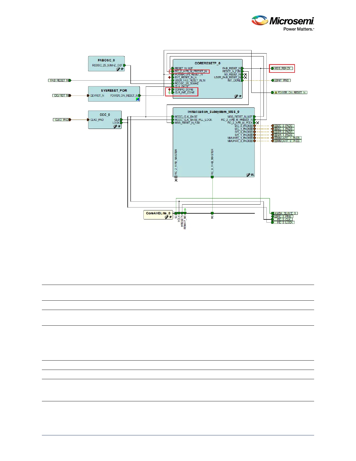
Figure 308 • Initialization Sub-system for FIC Sub-systems
21.5 SYSREG Control Registers
The description of registers are located in the SYSREG section of the user's guide and are listed in the
following table. Refer to the System Register Block, page 670 for a detailed description of each register
and bit.
Table 648 • Switch Register Map
Register Name
Register
Type
Flash Write
Protect Reset Source Description
GPIO_SYSRESET_SEL_CR RW-P Register PORESET_N Configures the GPIO system reset
SOFT_RESET_CR RW-P Bit SYSRESET_N Generates the software control resets
to the MSS peripherals
RESET_SOURCE_CR RW Reset source control register. The
source of Cortex-M3 processor reset
is captured in this register. The reset
values are mentioned in the bit
definitions.
MDDR_CR RW-P Register PORESET_N MDDR configuration register
WDOG_CR RW-P Register PORESET_N It configures Watchdog timer
MSSDDR_FACC1_CR RW-P Field CC_RESET_N MSS DDR Bridge fabric alignment
clock controller 1 configuration
register