RTC System
UG0331 User Guide Revision 15.0 606
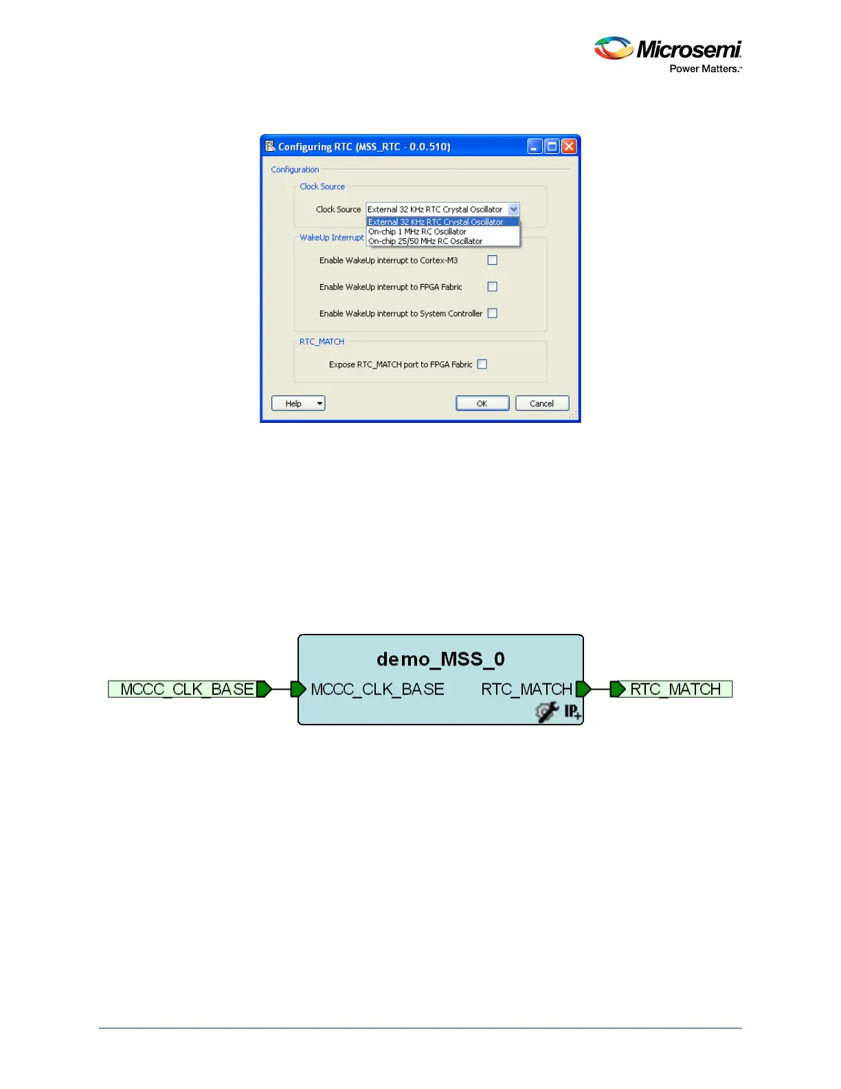
2. Clicking RTC displays the RTC configuration window, as shown in the following figure.
Figure 257 • RTC Configuration Window
• Select the Clock Source that drives the RTC system (RTCCLK) as either External 32 KHz RTC
crystal oscillator, or On-chip 1 MHz RC oscillator, or On-chip 25/50 MHz RC oscillator (50 MHz
in 1.2 V part)
• Select the Wake-Up Interrupt. The RTC_WAKEUP_CR in the SYSREG block provides
masking for the RTC_WAKEUP interrupt to the FPGA fabric, the Cortex-M3 processor, and the
system controller. The interrupt to be enabled can be selected using this configurator.
• Select the RTC_MATCH. The RTC_MATCH status bit and output is asserted whenever the
Alarm system is enabled and a match occurs. In Calendar mode, it is asserted for a 1 second
period while the alarm condition is valid. The output is synchronous to the rising edge of the
RTCCLK. The RTC_MATCH output signal can be exposed to drive the FPGA fabric. The
RTC_MATCH signal is then available to be used in the design.
3. The RTC signals in top level instance are shown in the following figure.
Figure 258 • RTC Signals