Universal Serial Bus OTG Controller
UG0331 User Guide Revision 15.0 350
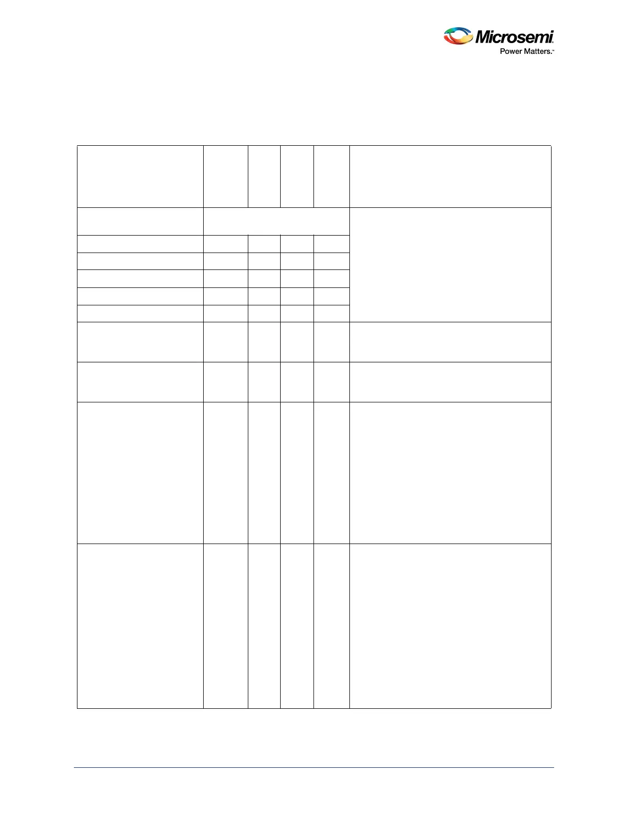
10.3.11 Extended Registers
These registers correspond to extended register set. This section covers all registers in this category
along with the address offset, functionality, and per bit details.
Table 284 • Extended Registers Description
Register Name
Address
Offset
from
0x40043
000 Width
R/W
Type
Reset
Value Description
EPx_RQ_PKT_COUNT_REG
(0x40043XYZ)
This read/write register is used in Host mode to
specify the number of packets that are to be
transferred in a block transfer of one or more
bulk packets of length MaxP
(EPx_RX_MAX_P_REG) to receive endpointx.
The core uses the value recorded in this register
to determine the number of requests to issue
where the AutoReq option (RX_CSRH_REG.bit
6 has been set.
EP0_RQ_PKT_COUNT_REG 0x0300 16 RW 0
EP1_RQ_PKT_COUNT_REG 0x0304 16 RW 0
EP2_RQ_PKT_COUNT_REG 0x0308 16 RW 0
EP3_RQ_PKT_COUNT_REG 0x030C 16 RW 0
EP4_RQ_PKT_COUNT_REG 0x0310 16 RW 0
RX_DPKT_BUF_DIS_REG
(0x40043340)
0x0340 16 RW 0 Indicates which of the receive endpoints (EP0,
EP1, EP2, EP3, EP4) have disabled the double
packet buffer functionality.
TX_DPKT_BUF_DIS_REG
(0x40043342)
0x0342 16 RW 0 Indicates which of the transmit endpoints (EP0,
EP1, EP2, EP3, EP4) have disabled the double
packet buffer functionality.
C_T_UCH_REG
(0x40043344)
0x0344 16 RW N/A Sets the chirp timeout. This number when
multiplied by 4 represents the number of XCLK
cycles before the timeout occurs. That is, if
XCLK is 30 MHz, this number represents the
number of 133 ns time intervals before the
timeout occurs. If XCLK is 60 MHz, this number
represents the number of 67 ns time intervals
before the timeout occurs. Although this bit is
written by the host in the CLK domain, the
counter that utilizes this value is in the XCLK
domain. No time domain crossing is provided
because the value in this register is a static.
C_T_HHSRTN_REG
(0x40043346)
0x0346 16 RW N/A Sets the delay from the end of high speed
resume signaling (acting as a Host) to enable
the UTM normal operating mode. This number
when multiplied by 4 represents the number of
XCLK cycles before the timeout occurs. That is,
if XCLK is 30 MHz, this number represents the
number of 33.3 ns time intervals before the
timeout occurs. If XCLK is 60 MHz, this number
represents the number of 16.7 ns time intervals
before the timeout occurs. Although this bit is
written by the host in the CLK domain, the
counter that utilizes this value is in the XCLK
domain. No time domain crossing is provided
because the value in this register is a static.