RTC System
UG0331 User Guide Revision 15.0 603
18.2.1.3 Alarm Wake-up Comparator
The RTC has two modes of operation, selectable through the clock_mode bit (Table 605, page 609).
In Calendar mode, the RTC counts seconds, minutes, hours, days, month, years, weekdays, and weeks.
In Binary mode, the RTC consecutively counts from 0 all the way to 2
43
. In both the modes, the alarm
event generation logic simply compares the content of the Alarm register with that of the RTC; when they
are equal, the RTC_MATCH output is asserted.
18.2.2 Port List
The following table lists the ports of the RTC and provides a short description for each.
18.2.2.1 Reset
The RTC is reset with the power-on reset (poreset_n) signal. Subsequent soft resets of the MSS do not
reset the RTC. For further details, refer to the Reset Controller, page 642.
18.2.2.2 Clocking
The RTC has two clock inputs:
• RTCCLK: This is used to clock the RTC.
• PCLK: This is used for the CPU interface.
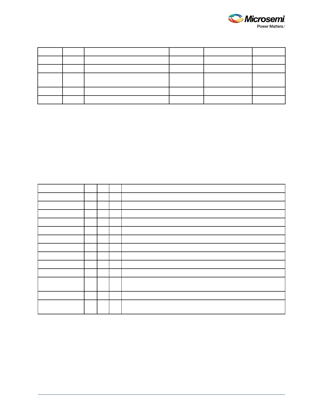
Hour 5 0-23 0-31 0 0
Day 5 1-31 (auto adjust by month and year) 0-31 1 0
Month 4 1-12 0-15 1 0
Year 8 0-255
Year 2000 to 2255
0-255 0 (year 2000) 0
Weekday 3 1-7 0-7 1 0
Week 6 1-52 0-63 1 0
Table 602 • RTC Interface Signals
Port MSB LSB Dir Description
PCLK in APB interface clock.
PRESETN in Processor reset
PADDR 6 0 in APB address. Registers are word aligned so A1:0 is not used.
PSEL in APB select signal
PENABLE in APB enable
PWRITE in APB write signal
PWDATA 31 0 in APB write data bus
PREADY out APB ready signal; is always asserted
PRDATA 31 0 out APB read data bus
RTC_MATCH out RTC match output (active high) Synchronous to clk 32 k.
RTC_WAKEUP out RTC wake up interrupt (active high). Asserted Synchronous to clk 32 k, but
deasserted on positive edge of PCLK.
CLKRTC in Clock input for RTC counters
PORST_B in Power-on reset. It clears/preset all flip-flops including the calendar/prescaler
counters (active low).
Table 601 • Calendar Counter Description (continued)