System Register Block
UG0331 User Guide Revision 15.0 704
22.3.36.1 FACC_PLL_RANGE
22.3.37 MSS DDR PLL Status High Configuration Register
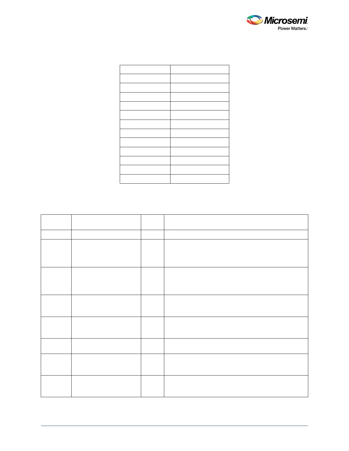
Table 692 • FACC_PLL_RANGE
Bits[23:19] PLL Range
0000 Bypass
0111 18–29 MHz
0001 1–1.6 MHz
1000 29–46 MHz
0010 1.6–2.6 MHz
1001 46–75 MHz
0011 2.6–4.2 MHz
1010 75–120 MHz
0100 4.2–6.8 MHz
1011 120–200 MHz
0101 6.8–11 MHz
0110 11–18 MHz
Table 693 • MSSDDR_PLL_STATUS_HIGH_CR
Bit Number Name
Reset
Value Description
[31:13] Reserved 0
[12:8] FACC_PLL_SSMF 0 Drives the spread spectrum modulation frequency (SSMF)
input of the MPLL. The only allowable value to be programmed
in this field is 0, as spread spectrum mode is not supported for
the MPLL.
[7:6] FACC_PLL_SSMD 0 Drives the spread spectrum modulation depth (SSMD) input of
the MPLL. The only allowable value to be programmed in this
field is 0, as spread spectrum mode is not supported for the
MPLL.
5 FACC_PLL_SSE 0 Drives the SSE input of the MPLL. The only allowable value to
be programmed in this field is 0, as spread spectrum mode is
not supported for the MPLL.
4 FACC_PLL_PD 0 A PD signal is provided for lowest quiescent current. When PD
is asserted, the MPLL powers down and outputs will be Low.
PD has precedence over all other functions.
3 FACC_PLL_FSE 0 Configures PLL internal and external feedback paths. The only
allowed value to be programmed in this field is 1.
2 FACC_PLL_MODE_3V3 0x1 Configures MPLL analog operational voltage.
1: 3.3 V
0: 2.5 V
1 FACC_PLL_MODE_1V2 0x1 Configures the PLL core voltage.
1: 1.2 V
Do not write to this field.