Cache Controller
UG0331 User Guide Revision 15.0 139
4.2.3.3 Cache Engine
The Cache Engine takes care of address generation logic using a four-way set associative, hit and miss
generation logic, cache line filling/replacement, a temporary local buffer for cache line while writing, and
arbitration logic for ICode and DCode buses.
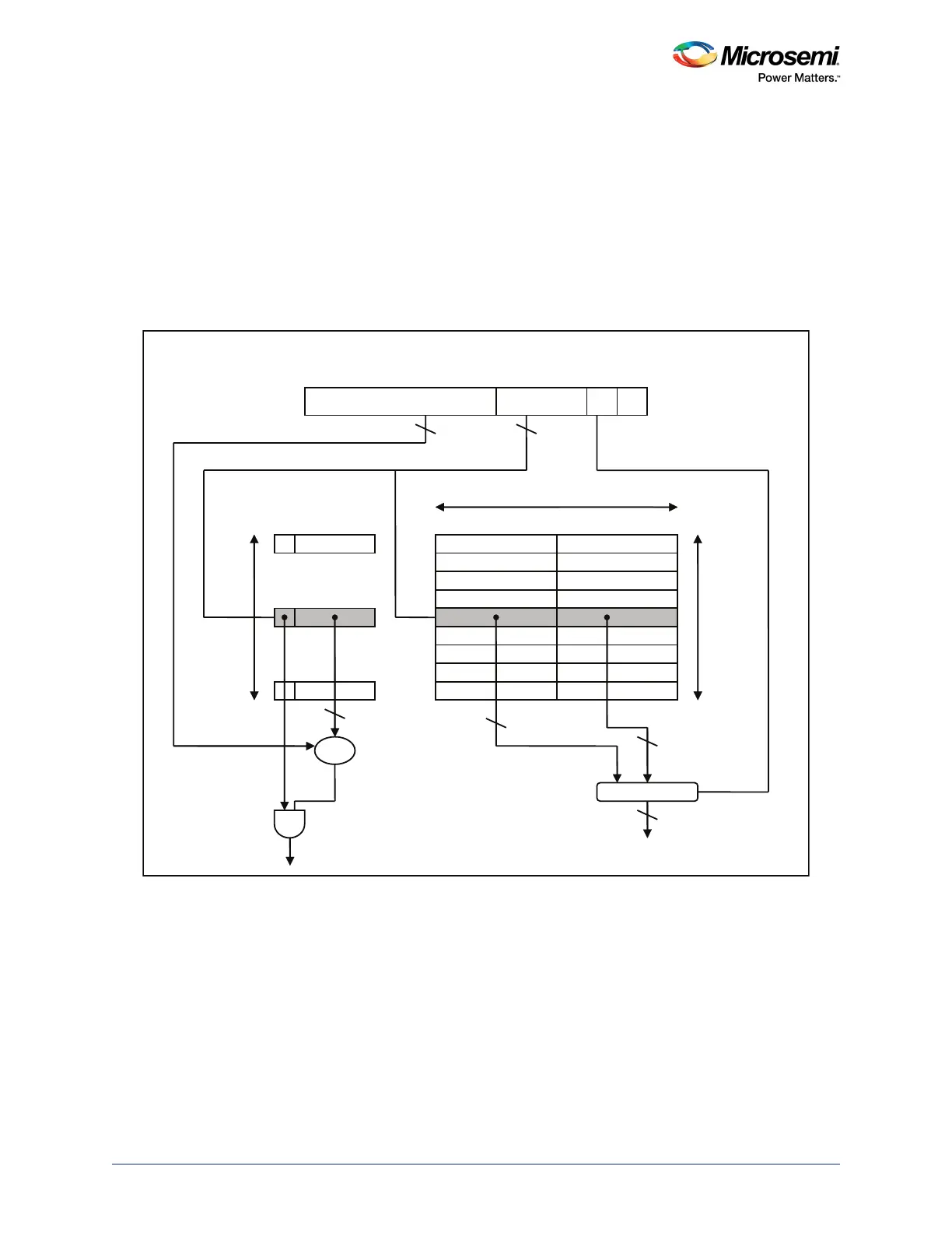
The Cache Controller has a four-way set associative cache subsystem with 32-byte cache lines
organized as 64 sets of 4 cache lines. Eight bits from the memory address (shown in the following figure)
select one of these 256 different locations. The Cache Controller can map a block of 32 data bytes to any
of the cache lines, replacing the LRU block. As one location of the memory contains 64-bit information
the required data can be selected by using the second bit from the memory address as shown in the
figure.
Figure 58 • General Cache Architecture and Addressing
The Cache Engine has two buses interacting with the ICode and DCode buses through interfaces MS3
and MS4. It supports the following functionalities:
1. Only read transfers from ICode and DCode bus are cached
2. 32 bytes local buffering of cache line read from slave
3. Support 32-/128-bit local interface on the AHB master side
4. All miss non-cacheable transactions targeted for eNVM are routed through MM4
5. Arbitration: In case of simultaneous access from ICode and DCode, all transactions from DCode are
processed before ICode is processed.
a. Supports full cache flush or index-based flushing
31 …… 11 10 … 3 2 1 0
256
Tag Data V
64 Bits
=
Hit
MUX
32
32
32
Data
21 8
Tag
Index
Block Offset
21
64
[10:5]
[10:3]