Cache Controller
UG0331 User Guide Revision 15.0 142
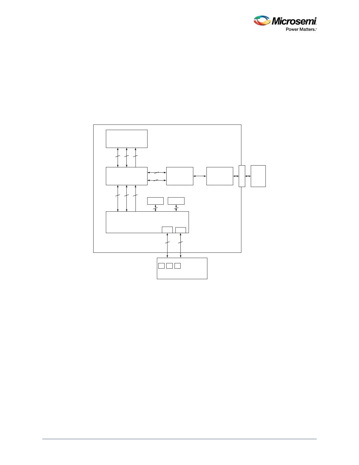
4.2.5 Interfaces
The following figure shows the Cache Controller interface in the MSS subsystem. There are two
interfaces through which the Cache Controller is connected to the main memories:
1. Interface towards MDDR bridge: 128-bit AHB-Lite, this interface is read only for instruction/data
reads and 32-bit AHB-Lite to access DDR memory through DDR bridge and system bus (read and
write access)
2. Interface towards AHB bus matrix: There are three 32-bit AHB-Lite modes:
• Read/write for non-cacheable data access to eSRAM/eNVM
• Read/write from SBus
• Read/write from ICode bus
Figure 61 • Cache Controller Interface
Cortex-M3
Processor
Cache Controller
MSS DDR
Bridge
MDDR
Subsystem
AHB Bus Matrix
S
SD
DI
IC
DS
IDC
D
D
R
I
O
eNVM eSRAM
DDR
SDRAM
64 - Bit
AXI
FPGA Fabric
Fabri c SR AM
FIC_0
32
32
32
32 32 32
32
128
MSS
FIC_1
32
32
32 32