MMUART Peripherals
UG0331 User Guide Revision 15.0 483
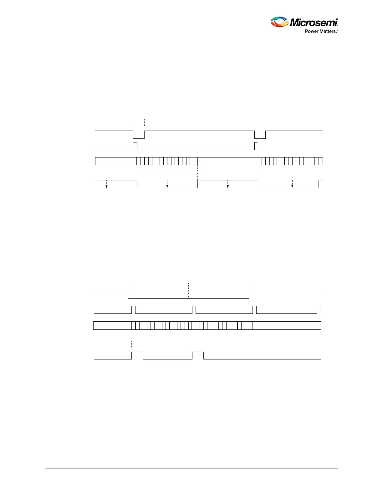
After input filtering, the demodulator waits for a positive edge and sets a down counter based on the
internal 16 samples per bit time baud rate clock. The output NRZ signal is set Low until the counter
reaches 0, then automatically it goes High.
When back-to-back pulses occur, the incoming pulse may not be aligned with the internal baud count
enable and as such may generate a 1/16 NRZ 1 level. This 1/16
th
pulse is a do not care situation
because the sampling occurs in the middle of the Tbit time (bit time).
The input to the demodulator can be an inverted version of the following figure using the EIRX
configuration bit in the multi-mode control register 1 (MM1). Also the EIRD bit in MM1 has to be set to 1.
Figure 192 • RX RZI-to-NRZ Demodulation
13.2.4.4.2 NRZ to RZI Modulation
The NRZ to RZI modulation receives the MMUART_X_TXD_nrz signal which is in NRZ format and needs
to be converted into the RZI format. The modulator waits for a negative edge on the NRZ signal, sets a
baud rate/16 decremented down counter and outputs a pulse for the first 3 or 4 counts. If the count
reaches zero and the NRZ signal is still Low, another output pulse is generated, otherwise, no pulse is
generated.
The output of the modulator can be an inverted version of the following figure with the EITX configuration
bit in the MM1. Additionally, the output can be 1/4 widths instead of 3/16
th
using the EITP bit. Also the
EIRD (enable bit RZI mod/demod) bit in MM1 has to be enabled. The following example shows an output
for a signal that has two consecutive zeros and the value of EIRD=1, EITX=1, and EITP=0.
Figure 193 • Tx NRZ-to-RZI Modulation
13.2.4.5 Transmitter Time Guard
When the transmitter time guard (TTG) feature is enabled and configured for a time value greater than 0,
it allows programmable wait periods between transmissions. It can be configured in the TTG register. On
each byte transfer, the transmitter enters a TTG wait state prior to sending out the stop bits. Tx Time
Guard Value = TTG x Bit Time (Tbit)
MMUART_X
_RXD_rzi
MMUART_X
_RXD_nrz
MMUART_X_
RXD_rzi_neg
br_dwn_cnt
internal
sample times
@ 8/16
3/16
16/16 = 1 Bit Time
10 A
C
DE
F1
23
4
5
69B78
00
0
10 ACDEF1234569B78
A
C
DE
F1
23
4
5
69B78
ACDE
F1
23
4
5
69B78
0
0
0
0
16/16 = 1 Bit Time
16/16 = 1 Bit Time
3/16
MMUART_X_
TXD_nrz
MMUART_X_
TXD_nrz_neg
br_dwn_cnt
MMUART_X_
TXD_nzi
Multi-Mode Config Bits in this example: EIRD = 1, EITX + 1, EITP = 0