Fabric Interface Controller
UG0331 User Guide Revision 15.0 757
24 Fabric Interface Controller
The fabric interface controller (FIC) enables connectivity between the fabric and microcontroller
subsystem (MSS). The FIC is a part of the MSS and performs a bridging function for AHB-Lite to APB or
AHB-Lite to AHB-Lite between the AHB bus matrix and the FPGA fabric. The interface type is
configurable. There are up to two, 32-bit FICs in SmartFusion2 devices, referred to as FIC_0 and FIC_1.
Both FICs provide two bus interfaces between the MSS and the fabric. The first is mastered by the MSS
and has slaves in the fabric; the second is mastered by the fabric and has slaves in the MSS.
The interfaces to the fabric can be 32-bit AHB-Lite or 32-bit APB. The address and data buses between
the FIC and the FPGA fabric are overlaid; hence, only one type of interface can be enabled at any time.
However, separate groups of signals are used for the AHB-Lite and APB control signals. In addition to
the choice of AHBLite or APB interfaces between the MSS and the fabric, a number of options related to
relative clock frequencies and pipelining of transactions are available. Each FIC block can operate on a
different clock frequency, defined as a ratio of the MSS main clock, M3_CLK.
The SmartFusion2 architecture imposes a certain number of rules related to clocking domains between
the fabric interfaces and the FPGA fabric. This document provides guidance on how to properly construct
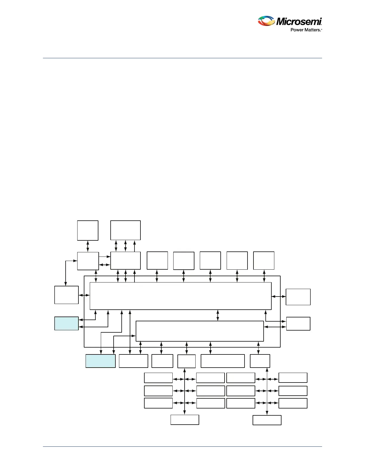
such systems. The following figure depicts the connectivity of FIC_0 and FIC_1 to the AHB bus matrix.
AHB-Lite master interface and AHB-Lite slave interface of FIC_0 is directly connected with mirrored
master 4 (MM4) and mirrored slave 4 (MS4) on the AHB bus matrix. To reduce the load on the AHB bus
matrix, FIC_1 AHB-Lite slave interface is connected through the synchronous AHB-to-AHB bridge with
an address decoder which inserts a one-cycle delay in each direction.
Figure 326 • The FIC Connection to the AHB Bus Matrix
AHB Bus Matrix
eSRAM_0
System
Controller
Cache
Controller
SD IC
ARM Cortex-M3
Processor
SDI
MSS DDR
Bridge
PDMA
MS6
MM3
AHB To AHB Bridge with Address Decoder
USB OTG
HPDMA
MDDR
APB_0
SYSREG
Triple Speed
Ethernet MAC
FIC_0
MM4 MS4
MS2 MS3 MS0
MS5
MS1
MM5 MM6
MM7
MM8
MM2 MM1 MM0 MM9
IDC
D/S
eNVM_0 eNVM_1 eSRAM_1
FIC_2 (Peripheral
Initialization)
APB_1
MMUART_0
SPI_0
I2C_0
PDMA
Configuration
WATCHDOG
FIIC
TIMERx2
MMUART_1
SPI_1
I2C_1
GPIO
CAN
RTC
COMM_BLK
FIC_1
MSS_FIC
MS6_USB
MS5_MAC MS5_SR MS5_APB0 MS5_FIC2 MS5_APB1