System Timer
UG0331 User Guide Revision 15.0 614
19 System Timer
The SmartFusion2 system timer (hereinafter referred as timer) consists of two programmable 32-bit
decrementing counters that generate interrupts to the Cortex-M3 processor and FPGA fabric. The two
32-bit timers are identical. X is used as a placeholder for 1, 2, or 64 in register descriptions. It indicates
Timer 1, Timer 2, or Timer 64.
19.1 Features
The timer has the following features:
• Three count modes: One-shot and Periodic
• Decrementing 32-bit counters
• Two 32-bit timers can be concatenated to create a 64-bit timer.
• Option to enable or disable the interrupt requests when timer reaches zero.
• Controls to start, stop, and reset the timer
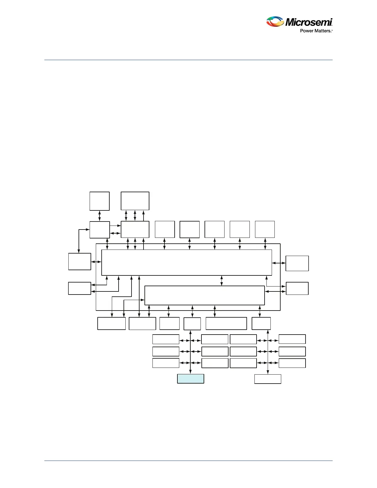
The following figure shows details of the MSS. Timer peripherals are connected to the AHB bus matrix
through the APB_0 interface.
Figure 261 • MSS Showing Timer Peripherals
19.2 Functional Description
This section provides detailed description of the timer.
19.2.1 Architecture Overview
The timer is an APB_0 slave that provides two programmable, interrupt generating, 32-bit decrementing
counters, as shown in the following figure.
AHB Bus Matrix
eSRAM_0
System
Controller
Cache
Controller
SD IC
ARM Cortex-M3
Processor
SDI
MSS DDR
Bridge
PDMA
MS6
MM3
AHB To AHB Bridge with Address Decoder
USB OTG
HPDMA
MDDR
APB_0
SYSREG
Triple Speed
Ethernet MAC
FIC_0
MM4 MS4
MS2 MS3 MS0
MS5
MS1
MM5 MM6
MM7
MM8
MM2 MM1 MM0 MM9
IDC
D/S
eNVM_0 eNVM_1 eSRAM_1
FIC_2 (Peripheral
Initialization)
APB_1
MMUART_0
SPI_0
I2C_0
PDMA
Configuration
WATCHDOG
FIIC
TIMERx2
MMUART_1
SPI_1
I2C_1
GPIO
CAN
RTC
COMM_BLK
FIC_1
MSS_FIC
MS6_USB
MS5_MAC MS5_SR MS5_APB0 MS5_FIC2 MS5_APB1