MMUART Peripherals
UG0331 User Guide Revision 15.0 475
The three major baud rate generation modes are listed below:
1. Fractional Baud Rate Generation–Asynchronous and Synchronous–Master Mode: The baud
rate generation follows asynchronous operation, but with an averaging function which yields more
precise, overall baud rate values in fractions of system clock cycles.
2. Clock-In Adaptation–Synchronous–Slave Mode: In this mode, the MMUART_X_SCK_IN (serial
input synchronous clock) determines the baud rate. MMUART may receive and transmit data based
on this clock (full-duplex).
3. Clock-Out Generation–Synchronous–Master Mode: In this mode, MMUART_X_SCK_OUT
(serial output synchronous clock) determines baud rate based on the baud rate registers. MMUART
may receive and transmit data based on this clock (full duplex).
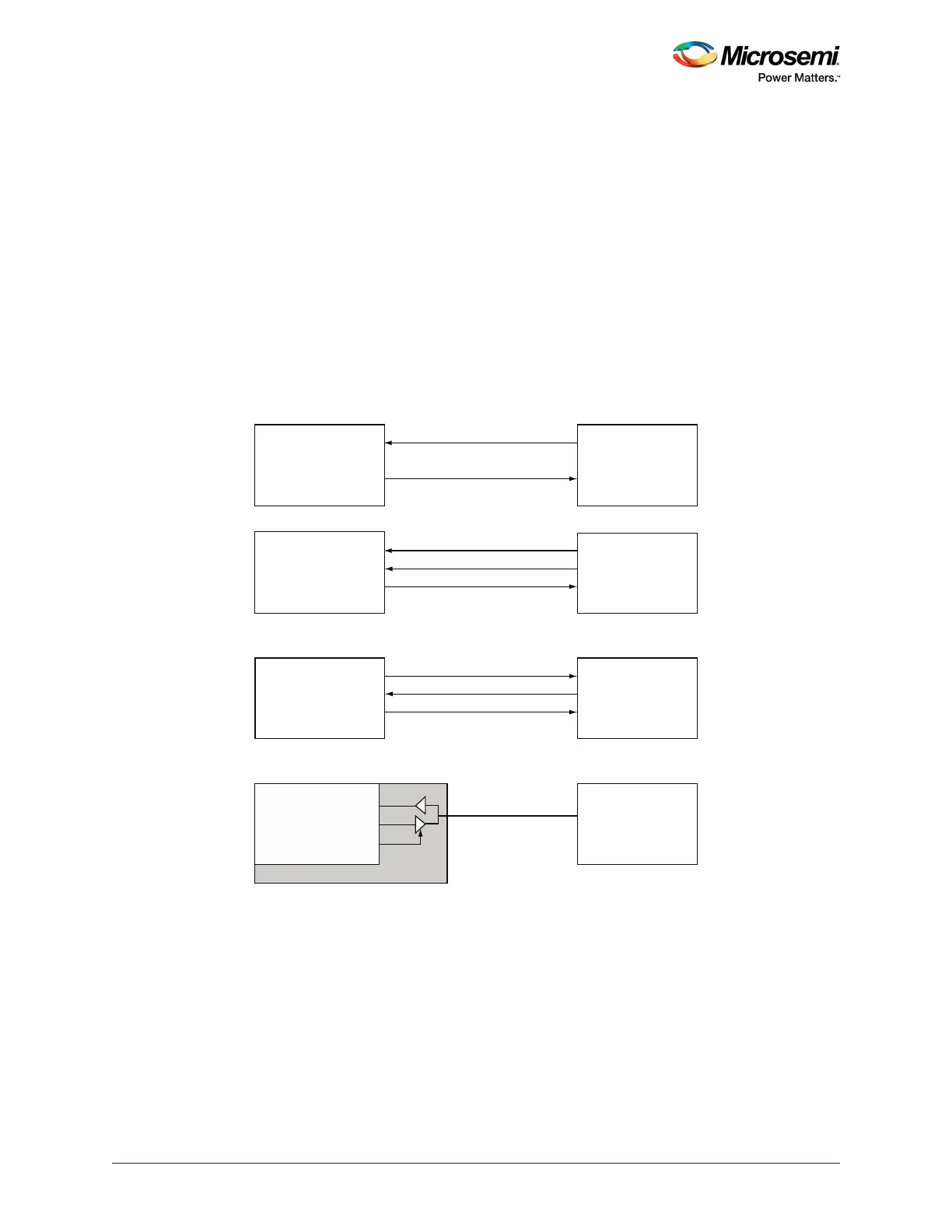
Software may drive half-duplex communication based on the application, and a single line may be used
for MMUART_X_TXD and MMUART_X_RXD transmissions through a bi-directional pad. While
transmitting data, the reception is inhibited and vice-versa. This can be done by enabling the single-wire
half-duplex enable (MMUART_X_ESWM). The following figure illustrates different MMUART system
topologies.
Figure 180 • Synchronous and Asynchronous Mode Topologies
MMUART
MMUART
MMUART
SMARTFUSION2
MMUART
MMUART_X_SCK_OUT
MMUART_X_SCK_IN
SMART CARD
UART
USART
SPI
Full-Duplex Async
Full-Duplex Sync-Slave
Full-Duplex Sync-Master
Half-Duplex Sync-Master
S_IN_OUT
MMUART_X_RXD
MMUART_X_RXD
MMUART_X_RXD
MMUART_X_RXD
MMUART_X_TXD
MMUART_X_TXD
MMUART_X_TE
MMUART_X_TXD
MMUART_X_TXD
CLK_IN
DO
DIN
TX
TX
RX
RX
CLK_OUT