MMUART Peripherals
UG0331 User Guide Revision 15.0 496
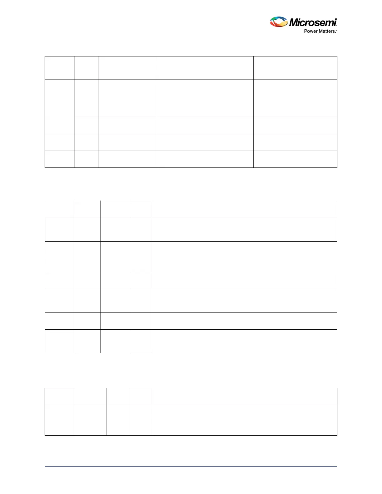
13.4.8 Multi-Mode Interrupt Identification Register (IIM)
13.4.9 Line Control Register (LCR)
0100 Second Received data
available
Receiver data available Reading the receiver buffer
register or the FIFO drops below
the trigger level.
1100 Second Character timeout
indication
No characters have been read from
the Rx FIFO during the last four
character times and there was at
least one character in it during this
time.
Reading the receiver buffer
register.
0010 Third Transmitter holding
register empty
Transmitter holding register empty Reading the IIR or writing into
the transmitter holding register.
0000 Fourth Modem status Clear to send, data set ready, ring
indicator, or data carrier detect
Reading the modem status
register.
0011 Fifth Multi mode interrupt Any of the multi-mode interrupts in the
IIM register.
Refer to Ta b le 4 79 , page 496
(IIM).
Table 479 • IIM
Bits Name R/W
Reset
Value Description
[7:5] Reserved Clean on R 0 Software should not rely on the value of a reserved bit. To provide
compatibility with future products, the value of a reserved bit should be
preserved across a read- modify-write operation.
4 LINSI Clean on R 0 LIN sync detection interrupt ID. This bit set when 5
th
falling edge is
detected by the sync timer. It resets the FIFO address pointers so that the
PID will be in the first location. Reading the IIM register clears this
interrupt.
3 LINBI Clean on R 0 LIN break interrupt, set automatically when break length of 11.5 Tbits is
detected. Reading the IIM register clears this interrupt.
2 PID_PEI Clean on R 0 Protected identifier field (PID) parity error interrupt is generated when
there is a mismatch in PID in LIN header, that is, when either the P0 or P1
bits in the incoming PID byte do not match the calculated P0 and P1 error.
1 NACKI Clean on R 0 NACK interrupt is asserted when EERR bit is set in MM2. Reading the
MM2 clears the interrupt.
0 RTOII Clean on R 0 Receiver time-out (RTO) interrupt ID. RTO interrupt is asserted when RTO
value is reached by the counter. It gets cleared when writing to the RTO
register.
Table 480 • LCR
Bit
Number Name R/W
Reset
Value Description
7 DLAB R/W 0 Divisor latch access bit. Enables access to the divisor latch registers
during read or write operation to address 0 and 1.
0: Disabled (default)
1: Enabled
Table 478 • Interrupt Identification Bit Values (continued)