Universal Serial Bus OTG Controller
UG0331 User Guide Revision 15.0 288
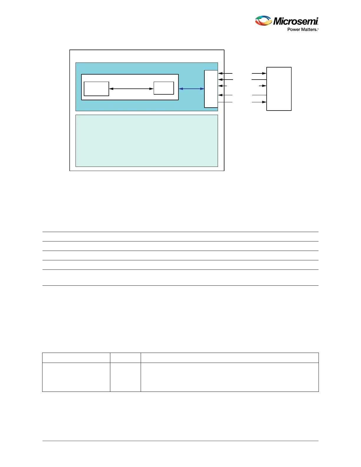
Figure 140 • Block Diagram for Connections between USB Controller and ULPI PHY through MSS
The ULPI interface is connected to the IOs of the device up to four separate sets of IOs. The function of
each IO in these sets is shared with another MSS function. These IO groups allow flexibility to the user in
deciding which MSS peripherals to connect to the IOs. The four USB IO groups are referred to as
USB_A, USB_B, USB_C and USB_D. User can try each USB IO group and see which pins cause
conflict and iterate through different assignments with the conflicting peripherals and GPIO. The
availability of these USB IO groups are device-dependent, as specified in the following table.
For more information on USB IO group, refer PPAT documents available at https://www.microsemi.com/product-directory/socfpgas/
1692-smartfusion2#documentation (PPAT documents are grouped under the section Pinout/Packaging in the above mentioned
site).
10.2.2.2 UTMI+ (USB 2.0 Transceiver Macrocell Interface+) Interface
This is the external interface connecting the SmartFusion2 USB OTG controller to an off-chip UTMI PHY
device. For UTMI interface, all the interface signals are routed through the FPGA fabric on to the MSIOs.
Table 191 • USB IO Group Availability
Device USB_A USB_B USB_C USB_D
M2S005 No Yes No No
M2S010 Yes Yes Yes No
M2S025 Yes Yes Yes No
M2S050 / 060 / 090 /
150
Yes Yes Yes Yes
Table 192 • UTMI+Interface Signals at Fabric Interface in SmartFusion2 Device
Signal Name Direction Description
UTMI_SUSPENDM Out Indicates asynchronous Suspend mode (derived from signals from both
CLK and XCLK flip-flops). When enabled through bit 0 of the Power
register, goes low when the device is in Suspend mode. Otherwise high
(intended to drive a UTMI PHY).
FABRIC
MSS
MUX/
DeMUX
ULPI
UTMI+ Level 3 / ULPI
Controller
Logic
USB Controller
MSIO
SmartFusion2
ULPI
_DATA
(
7:
0
)
ULPI
PHY
ULPI_CLK
ULPI_DIR
ULPI_STP
ULPI_NXT