AHB Bus Matrix
UG0331 User Guide Revision 15.0 210
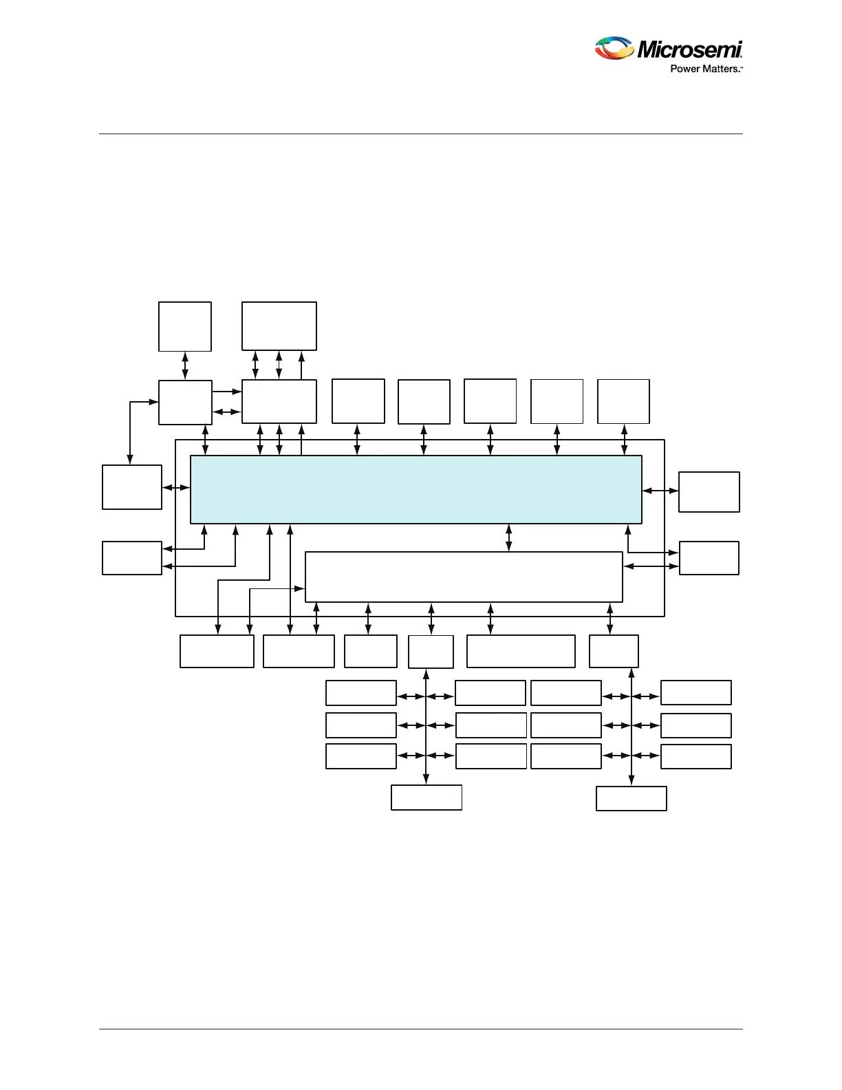
7 AHB Bus Matrix
The AHB bus matrix is a multi-layer AHB matrix. It is not a full crossbar switch, but a customized subset
of a full switch. It works purely as an AHB-Lite matrix. The SmartFusion2 SoC FPGA AHB bus matrix has
ten masters and seven direct slaves as depicted in the following figure. One master is permitted to
access a slave at the same time another master is accessing a different slave. If more than one master is
attempting to access the same slave simultaneously, arbitration for that slave is performed. Arbitration is
not purely round robin or weighted round robin (WRR), but it is a combination of priority, round robin for
processor-related masters and WRR for non-processor masters.
Figure 101 • AHB Bus Matrix Masters and Slaves
The preceding figure depicts the connectivity of masters and slaves in the AHB bus matrix.
Nomenclature such as MM0 and MS0 refers to a mirrored master and a mirrored slave. A mirrored
master port in the matrix connects directly to an AHB master; it has the same set of signals, but the
direction of the signals is described relative to the other end of the connection.
A mirrored slave port in the matrix connects directly to an AHB slave. Only a subset of the full set of
theoretical paths is implemented within the AHB bus matrix. The AHB bus matrix performs the address
decoding of all slaves except for slaves that connect to the AHB-to-AHB bridge.
AHB Bus Matrix
eSRAM_0
System
Controller
Cache
Controller
SD IC
ARM Cortex-M3
Processor
SDI
MSS DDR
Bridge
PDMA
MS6
MM3
AHB To AHB Bridge with Address Decoder
USB OTG
HPDMA
MDDR
APB_0
SYSREG
Triple Speed
Ethernet MAC
FIC_0
MM4 MS4
MS2 MS3 MS0
MS5
MS1
MM5 MM6
MM7
MM8
MM2 MM1 MM0 MM9
IDC
D/S
eNVM_0 eNVM_1 eSRAM_1
FIC_2 (Peripheral
Initialization)
APB_1
MMUART_0
SPI_0
I2C_0
PDMA
Configuration
WATCHDOG
FIIC
TIMERx2
MMUART_1
SPI_1
I2C_1
GPIO
CAN
RTC
COMM_BLK
FIC_1
MSS_FIC
MS6_USB
MS5_MAC MS5_SR MS5_APB0 MS5_FIC2 MS5_APB1