Fabric Interface Controller
UG0331 User Guide Revision 15.0 773
24.7.1.2.2 Master/APB
Instantiate and configure the CoreAPB3 bus as follows:
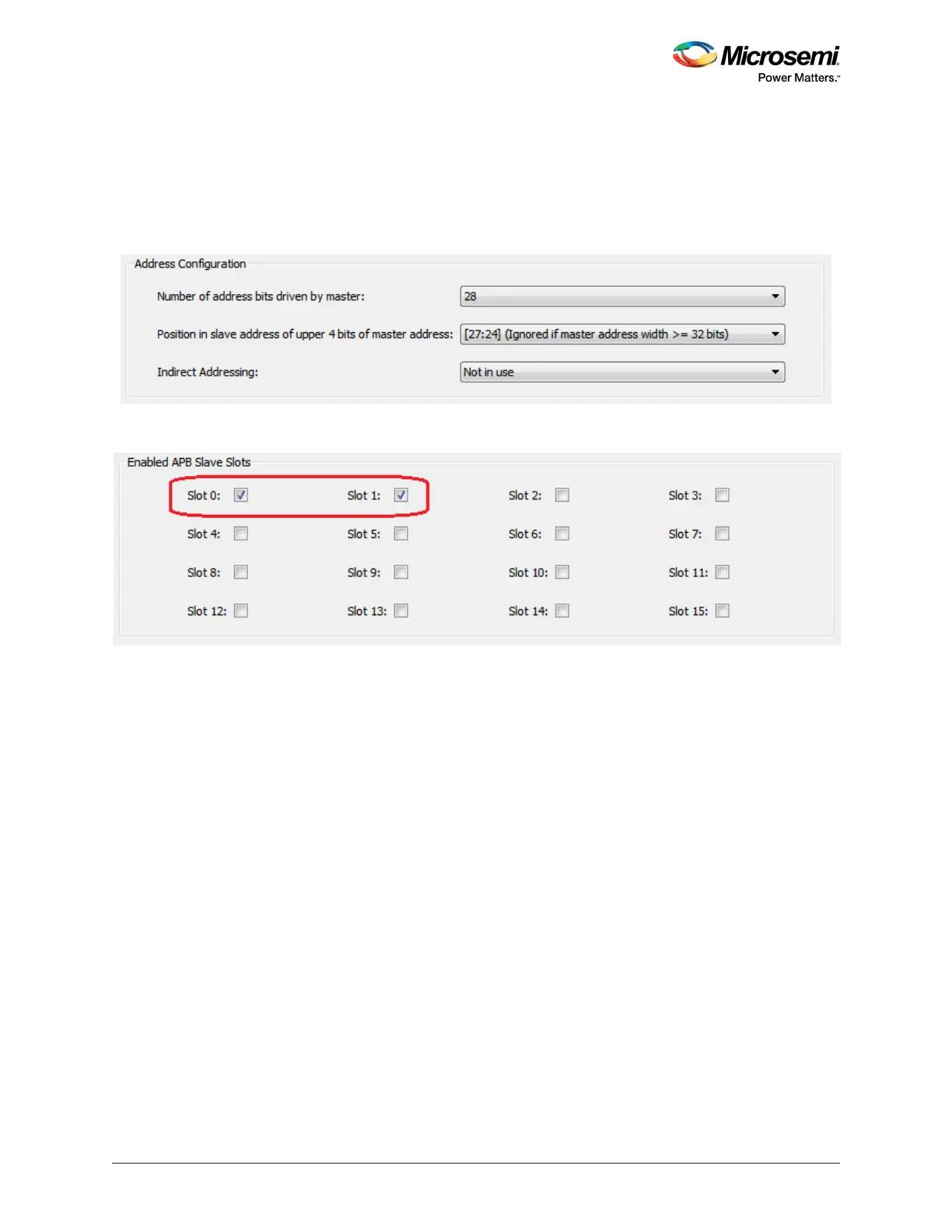
1. Select the Address Configuration options, as shown in the following figure. This mode provides
sixteen, 16 MB slots that can be used to connect up to sixteen APB compliant slaves. If you need
slots with more memory, you can combine multiple slaves to build a larger slot. Refer to the
CoreAPB3 User Guide for more details about this option.
Figure 346 • Master/APB Address Configuration
2. Enable the slots that you are planning on using for your application, as shown in the following figure.
Figure 347 • Master/APB Slave Slots Configuration
3. Instantiate and configure APB compliant peripheral cores and/or custom APB compliant
components.
4. Connect the subsystem together. this can be done in two ways.
Automatic Connection: Right-click in the top-level SmartDesign canvas and select the Auto Con-
nect option. This connects the FPGA fabric peripherals to the MSS FIC interfaces through the
CoreAPB3 bus.
Manual Connection:
• Connect the CoreAPB3 mirrored-master bus interface (BIF) port to the MSS master BIF port
(FIC_0/1_APB_MASTER), as shown in the following figure.
• Connect the APB slaves to the proper slots as per your memory map requirement.
• Clocks and resets; refer to the "Configuring the FIC Subsystem Clocks" section and
"Configuring the FIC Subsystem Reset" section on page 778.