MMUART Peripherals
UG0331 User Guide Revision 15.0 481
This serves as a start-of-frame notice to all nodes on the bus. The break field signals the start of a new
frame, as shown in the following figure.
Figure 188 • LIN Break Field Width => 11 Tbit Count Interrupt
The sync field is the second field transmitted by the master task in the header. Sync is defined as the
character x55. The sync field allows slave devices that perform automatic baud rate detection to
measure the period of the baud rate and adjust their internal baud rates to synchronize with the bus. The
sync field allows for fine calibration of the nominal baud rate, as shown in the following figure. After the
LINBI bit is set in multi-mode interrupt register (IIM), the first falling edge resets the sync timer and the
fifth falling edge stops counting. The 23-bit count value is divided by 128 (128 = 16 baud clocks per bit X
8 bits) to generate the integer baud rate by shifting the count value by seven towards LSB. The fractional
value is contained in the remaining bits, using the first insignificant bit to round the result.
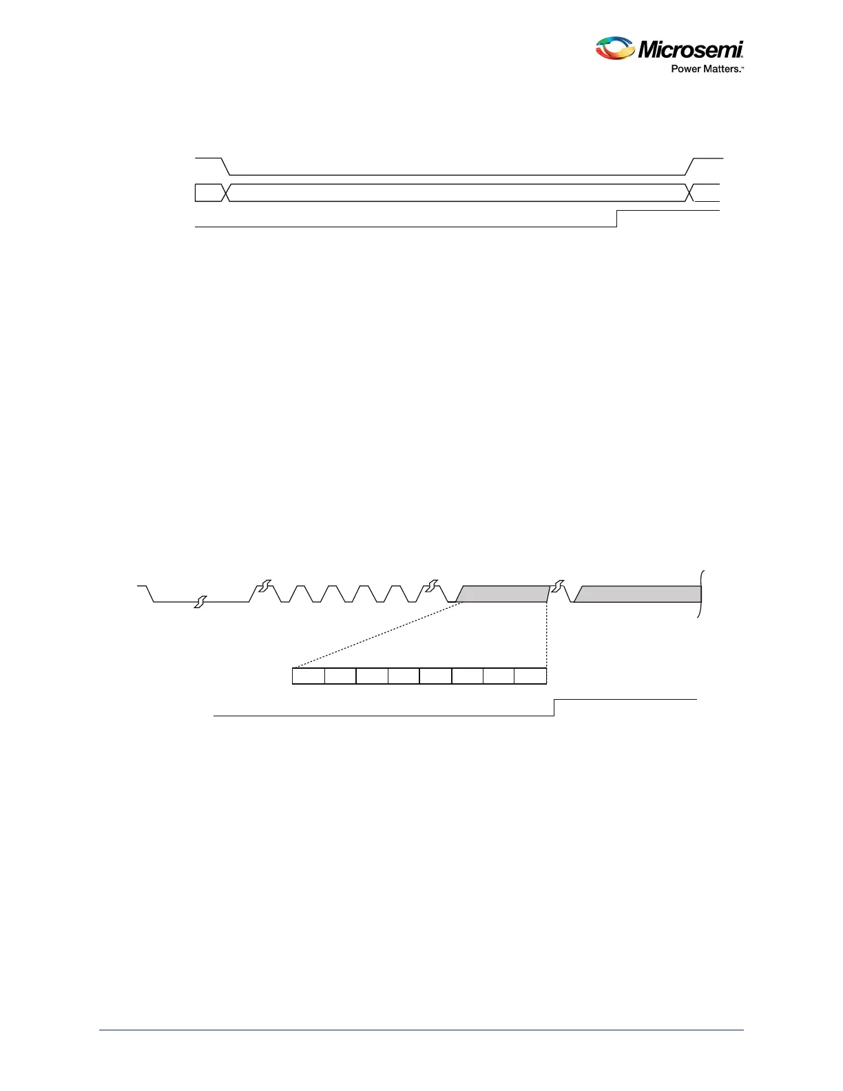
The PID field is the final field transmitted by the master task in the header. This field provides
identification for each message on the network and ultimately determines which nodes in the network
receive or respond to each transmission. All slave tasks continually listen for PID fields, verify their
parities, and determine if they have to receive data or send data for this particular identifier. The LINSI
interrupt resets the FIFO address pointers so that the PID stays in the first location. The firmware reading
the PID byte determines, if the application needs to send or receive data, and the trigger level that needs
to be set. A PID parity error check is performed on the fly and the interrupt, PID_PEI, is asserted when
there is a mismatch between the incoming P0 and P1 parity bits and the calculated P0 and P1 parity.
The PID field shown in the following figure is processed as the first byte and placed in the receive FIFO.
The parity is calculated as per the equations shown, and an interrupt (PID_PEI) is generated, if there is a
mismatch between the calculated PID parity and the received PID parity.
Figure 189 • LIN PID Parity Error Interrupt
MMUART_X
_RXD
Break_Timer
LINBI
0
0
Break Field=13 Tbit Length
Break Timer Counting to atleast 11.5 Tbit, Resetting if SIN=1
Break Field
Sync Byte
PID
PID_PEI
Rest of Frame
PID Byte
ID3 P1P0ID4 ID5ID2ID1ID0
Parity Equations:
P0 = ID0+ID1+ID2+ID4
P1 = -(ID1+ID3+ID4+ID5)