Serial Peripheral Interface Controller
UG0331 User Guide Revision 15.0 532
14.4.3.8 SPI Slave Select Register
The following table describes the register that specifies the slave that has been selected.
[7:0] CLK_GEN R/W 0 Specifies the methodology used to calculate the SPICLK divider.
CLK_MODE = 0:
SPICLK = 1 / (2
CLK_GEN + 1
) where CLK_GEN = 0 to 15.
CLK_MODE = 1:
SPICLK = 1 / (2 × (CLK_GEN + 1)) where CLK_GEN = 0 to 255.
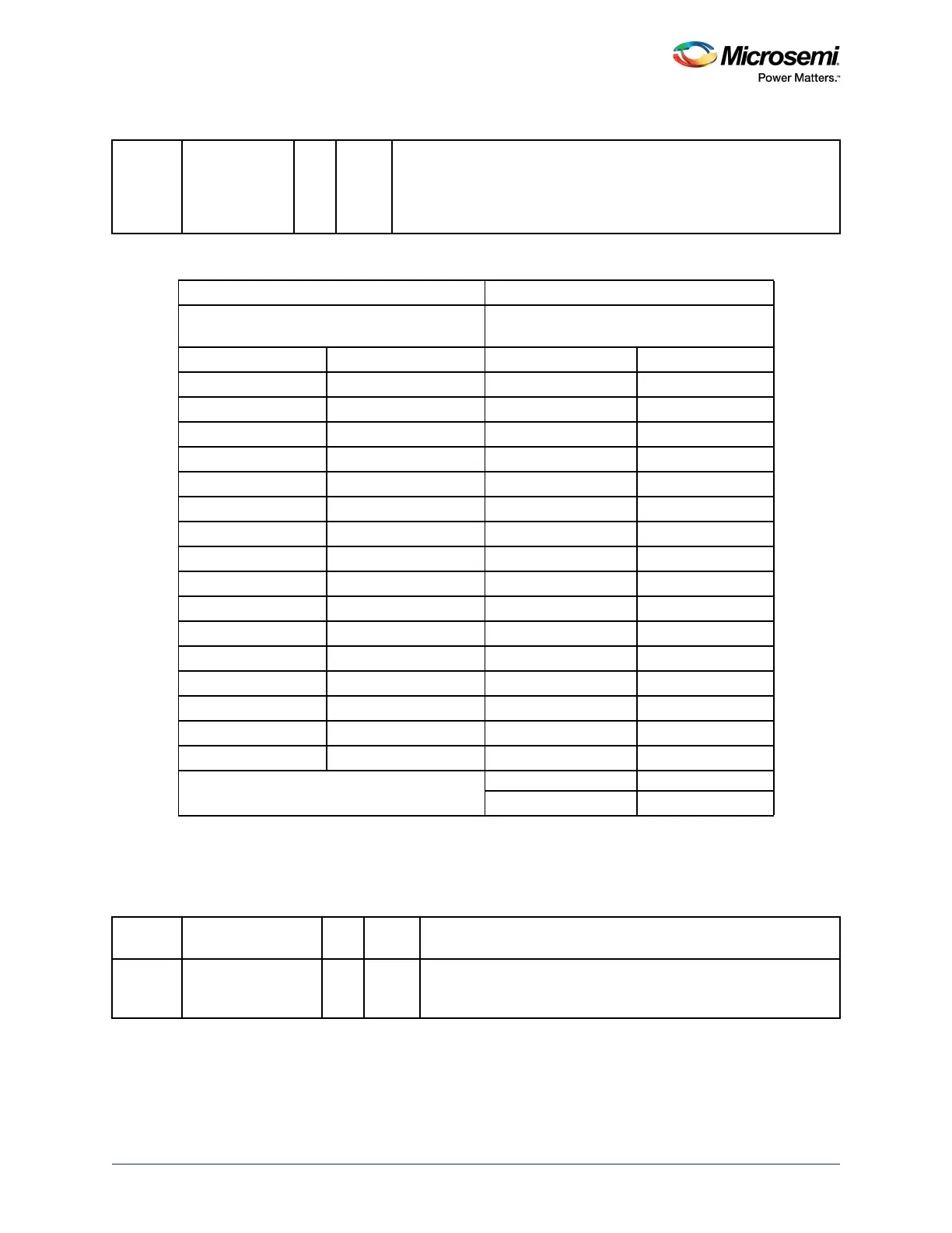
Table 507 • CLK_MODE Example, APB Clock = 153.8 MHz
CLK_MODE=0 CLK_MODE=1
SPICLK = 1 / (2
CLKRATE + 1
)
where CLKRATE = 0 to 15
SPICLK = 1 / (2 × (CLKRATE + 1))
where CLKRATE = 0 to 255
CLKRATE SPI Clock CLKRATE SPI Clock
0 76,900,000 0 76,900,000
1 38,450,000 1 38,450,000
2 19,225,000 2 25,633,333.33
3 9,612,500 3 19,225,000
4 4,806,250 4 15,380,000
5 2,403,125 5 12,816,666.67
6 1,201,562.5 6 10,985,714.29
7 600,781.25 7 9,612,500
8 300,390.625 8 8,544,444.444
9 150,195.312 9 7,690,000
10 75,097.656 10 6,990,909.091
11 37,548.828 11 6,408,333.333
12 18,774.414 12 5,915,384.615
13 9,387.207 13 5,492,857.143
14 4,693.603 14 5,126,666.667
15 2,346.801 15 4,806,250
…
…
255 300,390.625
Table 508 • SLAVE_SELECT
Bit
Number Name R/W
Reset
Value Description
[31:8] Reserved R/W 0 Software should not rely on the value of a reserved bit. To provide
compatibility with future products, the value of a reserved bit should
be preserved across a read-modify-write operation.
Table 506 • CLK_GEN (continued)