Serial Peripheral Interface Controller
UG0331 User Guide Revision 15.0 508
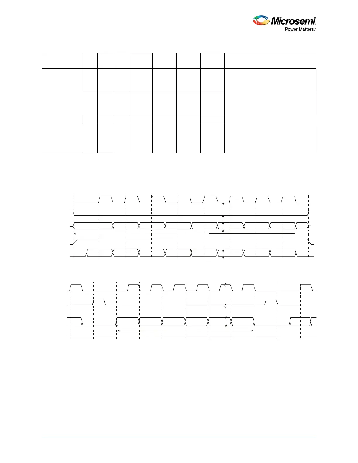
14.2.2.3.1 Motorola SPI Modes
Motorola SPI modes are shown in the following figures.
Single Frame Transfer – Mode 0: SPO = 0, SPH = 0
Figure 206 • Motorola SPI Mode 0
Multiple Frame Transfer – Mode 0: SPO = 0, SPH=0
Figure 207 • Motorola SPI Mode 0 Multiple Frame Transfer
Notes:
• Between frames, the slave select (SPI_SS[x]) signal is asserted for the duration of the clock pulse.
• Between frames, the clock (SPI_CLK) is Low.
• Data is transferred to most significant bit (MSB) first.
• The output enable (SPI_DOE_N) signal is asserted during the transmission and deasserted at the
end of the transfer (after the last frame is sent).
National
Semiconductor
Microwire
0 0 0 Low Rising Falling High Normal operation
SPI_X_CLK only generated with
select and data bits.
1 Low Rising Falling High Forces IDLE cycles (SPI_X_SS[0]
deactivated) between back-to-back
frames.
1 Running Rising Falling High SPI_X_CLK is free running.
1 Low Rising Falling High After sending the command part of the
frame, the subsequent frames are
concatenated to create a single large
data frame (master operation only).
Table 494 • Summary of Master SPI Modes (continued)
Mode SPS SPO SPH
Clock in
Idle
Sample
Edge
Shift
Edge
Select in
Idle Select Between Frames
SPI_CLK
SPI_DI
SPI_DO
SPI_DOE_N
SPI_SS[x]
MSB
LSB
LSB
MSB
4 to 32 Bits
Q
4 to 32 Bits
SPI_CLK
SPI_DI
SPI_DO
SPI_DOE_N
SPI_SS[x]
MSB
MSBLSBLSB