RTC System
UG0331 User Guide Revision 15.0 602
18.2 Functional Description
The following sections provide a detailed description of the RTC system.
18.2.1 Architecture Overview
This section describes the RTC architecture and its components which are as follows:
• Prescaler
• RTC Counter
• Alarm Wake-up Comparator
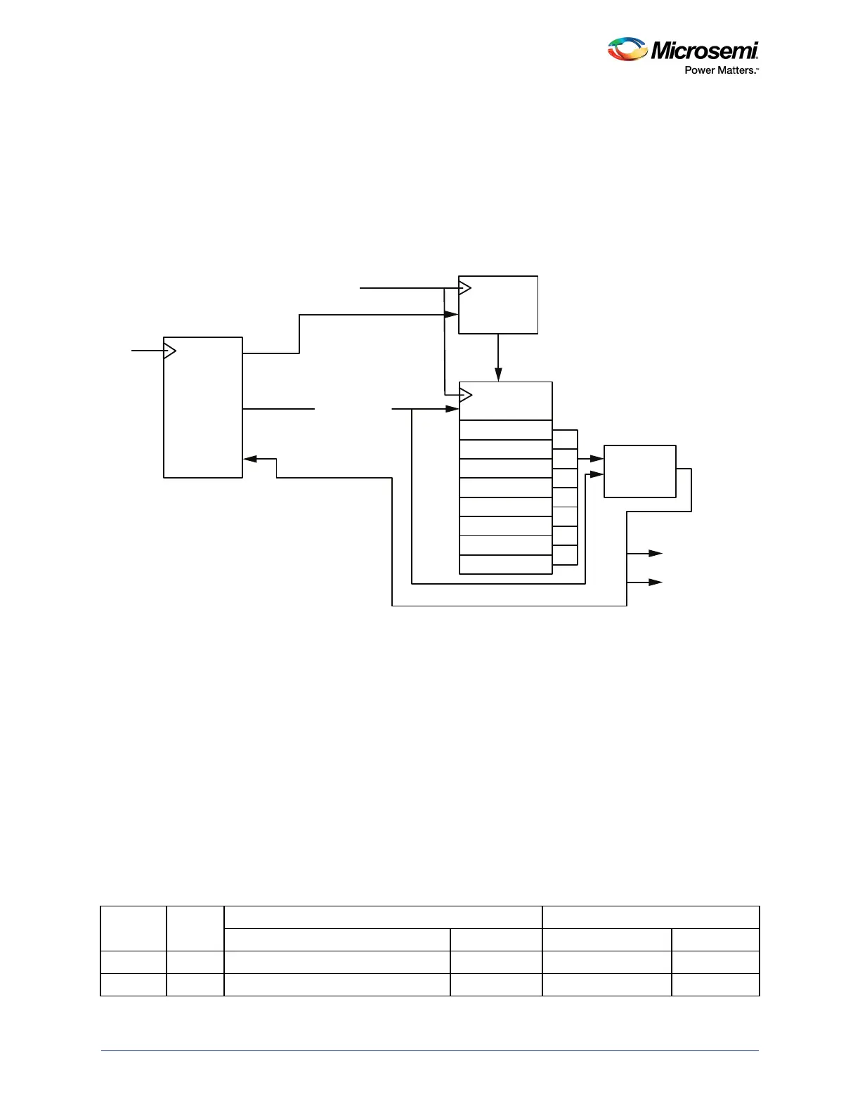
Figure 255 • RTC Block Diagram
18.2.1.1 Prescaler
The prescaler divides the input frequency to create a time-based strobe (typically 1 Hz) for the calendar
counter. The Alarm and Compare Registers, in conjunction with the calendar counter, facilitate
time-matched events.
To properly operate in Calendar mode, (Clock mode: 1), the 26-bit prescaler must be programmed to
generate a 1 Hz strobe to the RTC. In Binary mode, (Clock mode: 0), the prescaler can be programmed
as required in the application.
18.2.1.2 RTC Counter
The RTC counter keeps track of seconds, minutes, hours, days, weeks, and years when in Calendar
mode, and for this purpose it requires a 43-bit counter. When counting in Binary mode, the 43-bit register
is treated as a linear up counter.
The following table shows the details for Calendar mode and Binary mode.
Table 601 • Calendar Counter Description
Function
Number
of Bits
Range Reset Value
Calendar Mode Binary Mode Calendar Mode Binary Mode
Second 6 0-59 0-63 0 0
Minute 6 0-59 0-63 0 0
Seconds
Minutes
Hours
Day
Month
Year
Day of Week
Week
RTC Counter
Prescaler
APB
Registers
Configuration
Strobe 1 Hz
Enable
RTCCLK
PCLK
Alarm
Wake-up
Comparator
RTC_
MATCH
RTC_
WAKEUP