Ethernet MAC
UG0331 User Guide Revision 15.0 381
11.4 EMAC Operation
Before any DMA transfers can be carried out, two sets of descriptors are needed to be initialized in the
host memory. One descriptor is for the transmit operations and the other is for the receive operations.
Each set of descriptors takes the form of a linked list typically closed to form a ring buffer.
For ease of handling by software, the transfers are handled using linked lists of transmit and receive
descriptors. Transmit and receive descriptors define the buffer in the host memory for Tx operations and
another for Rx operations.
The transfer of data in either direction typically uses a ring buffer defined within host memory. The ring
buffer for the transmit operations is defined by a closed linked list of the Tx descriptors. The ring buffer for
the receive operations is defined by a closed link list of the Rx descriptors. The descriptors act as
pointers to the ring buffers. There are separate list of descriptors for both the transmit and receive
processes. Each descriptor is in the host memory.
The two ring buffers are formed of an equal-sized segment, each of which is 32-bit aligned and is
capable of storing a packet of up to the maximum size of packet transferred. Due to a limitation in the
AHB-DMA controller, Ethernet jumbo frames are not supported.
The software can either use the DMA Interrupts generated or poll semaphore bits within the descriptors
to maintain synchronization with the packet streams. The entry point into the buffer, used at the start of
any sequence of transfers, is given by the descriptor picked out by the DMATx/RxDescriptor register.
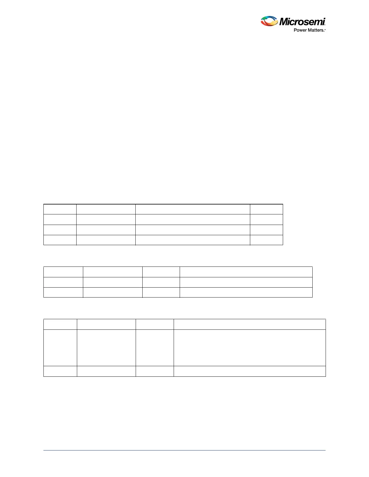
Each descriptor comprises a sequence of three 32-bit memory locations as shown in the following table.
Table 323 • Tx/Rx Descriptor
Address Register Function Size
0x0 PacketStartAddr Start address for the packet data. 32 bits
0x4 Packet Size Size of packet, Overrides and Empty Flag 32 bits
0x8 Next Descriptor Location of next descriptor 32 bits
Table 324 • PacketStartAddr
Bit Number Name Reset Value Description
[31:2] PacketStartAddr[31:2] 0x0 Start address of the packet.
[1:0] PacketStartAddr[1:0] 0x0 All transfers are 32-bit aligned in host memory.
Table 325 • Packet Size
Bit Number Name Reset Value Description
31 Empty Flag 0x0 For the transmit operations, this bit indicates the availability of
the data associated with the packet. For the receive
operations, this bit indicates the availability of the specified
location to store the received packet. The setting of this flag is
used to validate the descriptor.
[30:21] Reserved 0x0 Reserved