Peripheral DMA
UG0331 User Guide Revision 15.0 281
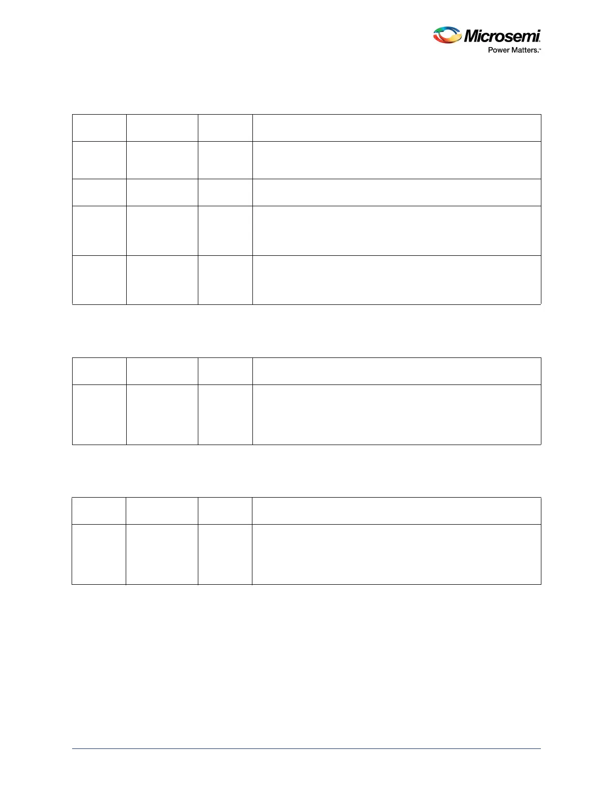
9.4.1.4 CHANNEL_x_STATUS Register Bit Definition
9.4.1.5 CHANNEL_x_BUFFER_A_SRC_ADDR Register Bit Definition
9.4.1.6 CHANNEL_x_BUFFER_A_DST_ADDR Register Bit Definition
Table 182 • CHANNEL_x_STATUS
Bit Number Name
Reset
Value Description
[31:3] Reserved 0 Software should not rely on the value of a reserved bit. To provide
compatibility with future products, the value of a reserved bit should be
preserved across a read-modify-write operation.
2 BUF_SEL 0 0: Buffer A is used
1: Buffer B is used
1 CH_COMP_B 0 Asserts when this channel completes its DMA. Cleared by writing to
CLR_COMP_B, bit 8 in CHANNEL_x_CONTROL register for this
channel. If INTEN is set for this channel, the assertion of CH_COMP_B
causes PDMAINTERRUPT to assert.
0 CH_COMP_A 0 Asserts when this channel completes its DMA. Cleared by writing to
CLR_COMP_A, bit 8 in CHANNEL_x_CONTROL register for this
channel. If INTEN is set for this channel, the assertion of CH_COMP_A
causes PDMAINTERRUPT to assert.
Table 183 • CHANNEL_x_BUFFER_A_SRC_ADDR
Bit Number Name
Reset
Value Description
[31:0] BUF_A_SRC 0 Start address from which data is to be read during the next DMA
transfer cycle. If PERIPHERAL_DMA = 1 and DIR = 0, this value is not
incremented from one DMA transfer cycle to the next. Otherwise, it is
always incremented by an amount corresponding to the
TRANSFER_SIZE for this channel.
Table 184 • CHANNEL_x_BUFFER_A_DST_ADDR
Bit Number Name
Reset
Value Description
[31:0] BUF_A_DST 0 Start address from which data is to be write during the next DMA
transfer cycle. If PERIPHERAL_DMA = 1 and DIR = 1, this value is not
incremented from one DMA transfer cycle to the next. Otherwise, it is
always incremented by an amount corresponding to the
TRANSFER_SIZE for this channel.