Inter-Integrated Circuit Peripherals
UG0331 User Guide Revision 15.0 552
15.4.2 Status Register
The following table describes the Status register of the I
2
C peripherals.
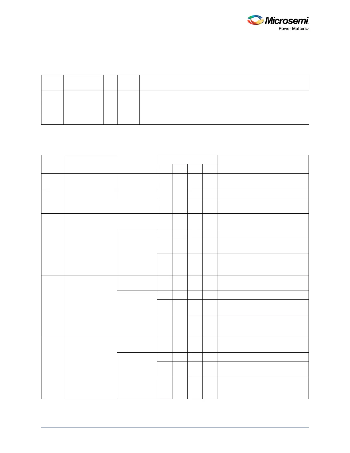
15.4.2.1 Status Register: Master-Transmitter Mode
Table 523 • Status Register (STATUS)
Bit
Number Name R/W
Reset
Value Description
7:0 Status register R 0XF8 The Status register is read-only. The status values depend on the mode of
operation. They are listed in Table 524, page 552 through Table 528 on
page 558. Whenever there is a change of state, interrupt is requested.
After updating any registers, the APB interface control must clear the
interrupt by clearing the SI bit of the Control Register (CTRL) register.
Table 524 • Status Register – Master-Transmitter Mode
Status
Code Status
Data Register
Action
Control Register Bits
Next Action Taken by CoreSTA STO SI AA
0x08 A START condition is
transmitted.
Load SLA+W 0 0 SLA+W is transmitted; ACK is received
0x10 A repeated START
condition is
transmitted.
Load SLA+W 0 0 SLA+W is transmitted; ACK is received
Load SLA+R 0 0 SLA+R is transmitted; Core is switched
to MST/REC mode.
0x18 SLA+W is transmitted;
ACK is received.
Load data byte 0 0 0 Data byte is transmitted; ACK is
received.
No action 1 0 0 Repeated START is transmitted
0 1 0 STOP condition is transmitted; STO
flag is reset.
1 1 0 STOP condition followed by a START
condition is transmitted; STO flag is
reset.
0x20 SLA+W is transmitted;
not ACK (NACK) is
received.
Load data byte 0 0 0 Data byte is transmitted; ACK is
received.
No action 1 0 0 Repeated START is transmitted
0 1 0 STOP condition is transmitted; STO
flag is reset.
1 1 0 STOP condition followed by a START
condition is transmitted; STO flag is
reset.
0x28 Data byte in Data
Register is
transmitted; ACK is
received.
Load data byte 0 0 0 Data byte is transmitted; ACK bit is
received.
No action 1 0 0 Repeated START is transmitted.
0 1 0 STOP condition is transmitted; STO
flag is reset.
1 1 0 STOP condition followed by a START
condition is transmitted; STO flag is
reset.