Universal Serial Bus OTG Controller
UG0331 User Guide Revision 15.0 290
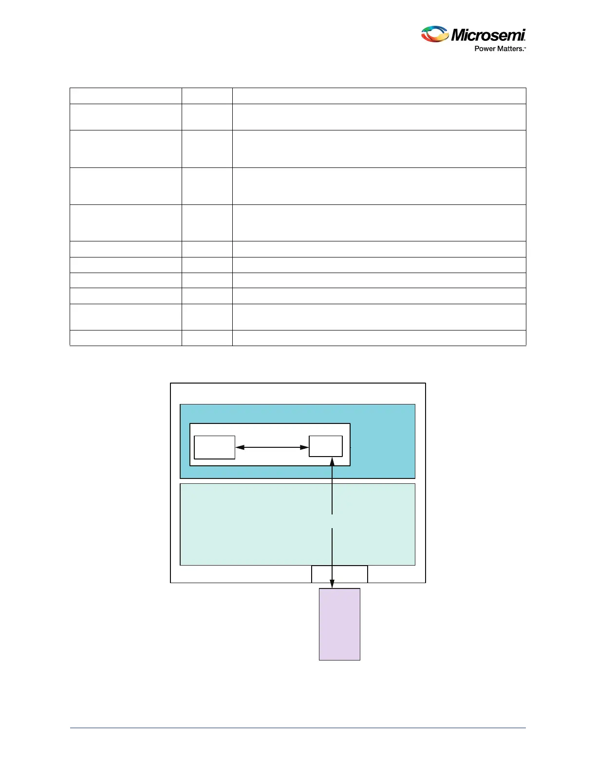
UTMI+Level3 signals are routed through the FPGA fabric onto MSIOs.
Figure 141 • Block Diagram for Connections Between USB Controller and UTMI PHY through FPGA Fabric
Note: The FPGA fabric design should implement a 'AND' logic between UTMI_TXVALID and UTMI_TXREADY
for proper data transmission.
UTMI_DISCHRGVBUS Out Discharges VBus (used by B devices to ensure that the VBus is low
enough before starting a session request protocol (SRP))
UTMI_HOSTDISCON In Host mode only; must be asserted when a high speed disconnect occurs
(in accordance with the UTMI+ specification).
Full/low speed connections are monitored through the LINESTATE signal.
UTMI_DPPULLDOWN Out Enables a pull-down resistor within the transceiver on the D+ line
– Low when the USB controller is operating as a peripheral
– High when USB controller is operating as a host
UTMI_DMPULLDOWN Out Enables a pull-down resistor within the transceiver on the D– line. Needs to
be high, when the USB controller is used for point-to-point
communications.
UTMI_IDDIG In Indicates USB controller connector type. High = B-type, Low = A-type.
UTMI_IDPULLUP Out Enables for IDDIG signal generation
UTMI_VSTATUS[7:0] In PHY status data; 8-bit wide as per UTMI+ specifications
UTMI_VCONTROL[3:0] Out PHY control data; 8-bit wide as per UTMI+ specifications
UTMI_VCONTROLLOADM Out Active low signal; asserted when new control information is required to be
read – if implemented
UTMI_RXVALIDH In Tied permanently low at the fabric interface
Table 192 • UTMI+Interface Signals at Fabric Interface in SmartFusion2 Device (continued)
Signal Name Direction Description
FABRIC
MSS
MUX/
DeMUX
UTMI
UTMI+ Level 3 / ULPI
Controller
Logic
USB Controller
MSIO
SmartFusion2
/26
UTMI
PHY