Fabric Interface Controller
UG0331 User Guide Revision 15.0 777
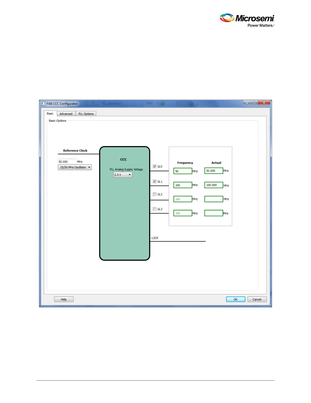
24.7.2.2 Step 2: Configure the FPGA Fabric FIC Clocks
Instantiate a CCC macro and configure it to satisfy the FIC subsystem clock rules, as described above.
Typically a global output (GLx) must be associated with each of the FIC clocks must be associated and a
frequency specified for each output matching the frequencies defined in the MSS_CCC configurator.
Microsemi recommends generating all the global outputs from a fabric PLL to guarantee the phase
alignment (as shown in Figure 351, page 777).
Note: If two FIC subsystems have the same frequencies, one fabric CCC global output is sufficient for clocking
both the FIC subsystems.
Figure 351 • Fabric Clocks Configuration
24.7.2.3 Step 3: Connect the FPGA Fabric FIC Subsystems Clock Networks
Connect the configured fabric CCC global outputs (GLx) to the associated FIC subsystems.
24.7.2.4 Step 4: Connect the MSS CLK_BASE Port
Connect the slowest of the fabric CCC global outputs (GLx) to MSS CLK_BASE port.
24.7.2.5 Step 5: Connect the MSS MCCC_CLK_BASE_PLL_LOCK Port
Connect the fabric CCC/PLL LOCK output to MSS MCCC_CLK_BASE_PLL_LOCK port.