Universal Serial Bus OTG Controller
UG0331 User Guide Revision 15.0 285
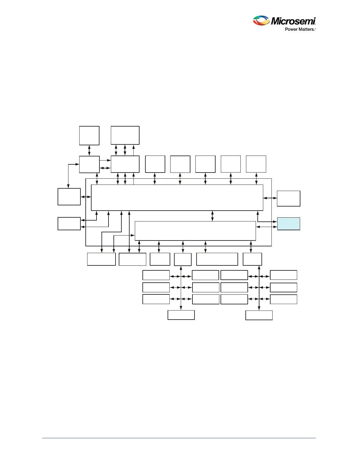
The following figure shows details of MSS. As shown in the figure, USB OTG controller can function as
an AHB master for DMA data transfers and as an AHB slave for configuring the USB OTG controller from
the masters ARM
®
Cortex
®
-M3 processor or from the FPGA fabric logic.
The SmartFusion2 USB OTG controller can function as:
• A high speed or a full speed peripheral USB device attached to a conventional USB host (such as a
PC)
• A point-to-point or multi-point USB host
• An OTG device that can dynamically switch roles from the host and the device
In all cases (USB host, USB device, or USB OTG), SmartFusion2 USB OTG supports control, bulk, ISO,
and interrupt transactions in all 3 modes.
Figure 138 • MSS Showing a USB OTG Controller
10.2 Functional Description
This section provides a detailed description of the USB OTG controller.
10.2.1 Architecture Overview
The following block diagram highlights the main blocks in the USB OTG controller. The USB OTG
controller is interfaced through the advanced high-performance bus (AHB) matrix in the MSS. The
SmartFusion2 USB OTG provides two interfaces (ULPI and UTMI) to connect to the external PHY.
Following are the main component blocks in the USB OTG controller:
• AHB Master and Slave Interfaces
• CPU Interface
• Endpoints (EP) Control Logic and RAM Control Logic
• Packet Encoding, Decoding, and CRC Block
AHB Bus Matrix
eSRAM_0
System
Controller
Cache
Controller
SD IC
ARM Cortex-M3
Processor
SDI
MSS DDR
Bridge
PDMA
MS6
MM3
AHB To AHB Bridge with Address Decoder
USB OTG
HPDMA
MDDR
APB_0
SYSREG
Triple Speed
Ethernet MAC
FIC_0
MM4 MS4
MS2 MS3 MS0
MS5
MS1
MM5 MM6
MM7
MM8
MM2 MM1 MM0 MM9
IDC
D/S
eNVM_0 eNVM_1 eSRAM_1
FIC_2 (Peripheral
Initialization)
APB_1
MMUART_0
SPI_0
I2C_0
PDMA
Configuration
WATCHDOG
FIIC
TIMERx2
MMUART_1
SPI_1
I2C_1
GPIO
CAN
RTC
COMM_BLK
FIC_1
MSS_FIC
MS6_USB
MS5_MAC MS5_SR MS5_APB0 MS5_FIC2 MS5_APB1