Cortex-M3 Processor (Reference Material)
UG0331 User Guide Revision 15.0 118
Flags in the BFSR indicate the cause of the fault, and whether the value in the BFAR is valid. See
BusFault Status Register, page 115.
3.7.2.17 Auxiliary Fault Status Register
The AFSR contains additional system fault information. See the register summary in Tab l e 50 , page 102
for its attributes.
This register is read, write to clear. This means that bits in the register read normally, but writing 1 to any
bit clears that bit to 0.
The bit assignments are:
Each AFSR bit maps directly to an AUXFAULT input of the processor, and a single-cycle HIGH signal on
the input sets the corresponding AFSR bit to one. It remains set to 1 until you write 1 to the bit to clear it
to zero.
When an AFSR bit is latched as one, an exception does not occur. Use an interrupt if an exception is
required.
3.7.2.18 System Control Block Design - Hints and Tips
Ensure software uses aligned accesses of the correct size to access the system control block registers:
• except for the CFSR and SHPR1-SHPR3, it must use aligned word accesses.
• for the CFSR and SHPR1-SHPR3 it can use byte or aligned halfword or word accesses.
The processor does not support unaligned accesses to system control block registers.
In a fault handler. to determine the true faulting address:
• Read and save the MMFAR or BFAR value.
• Read the MMARVALID bit in the MMFSR, or the BFARVALID bit in the BFSR. The MMFAR or BFAR
address is valid only if this bit is 1.
Software must follow this sequence because another higher priority exception might change the MMFAR
or BFAR value. For example, if a higher priority handler preempts the current fault handler, the other fault
might change the MMFAR or BFAR value.
3.7.3 System Timer, SysTick
The processor has a 24-bit system timer, SysTick, that counts down from the reload value to zero,
reloads (wraps to) the value in the SYST_RVR register on the next clock edge, then counts down on
subsequent clocks.
When the processor is halted for debugging the counter does not decrement.
The system timer registers are:
Table 70 • AFSR Bit Assignments
Bits Name Function
[31:0] IMPDEF Implementation defined. The bits map to the AUXFAULT input signals.
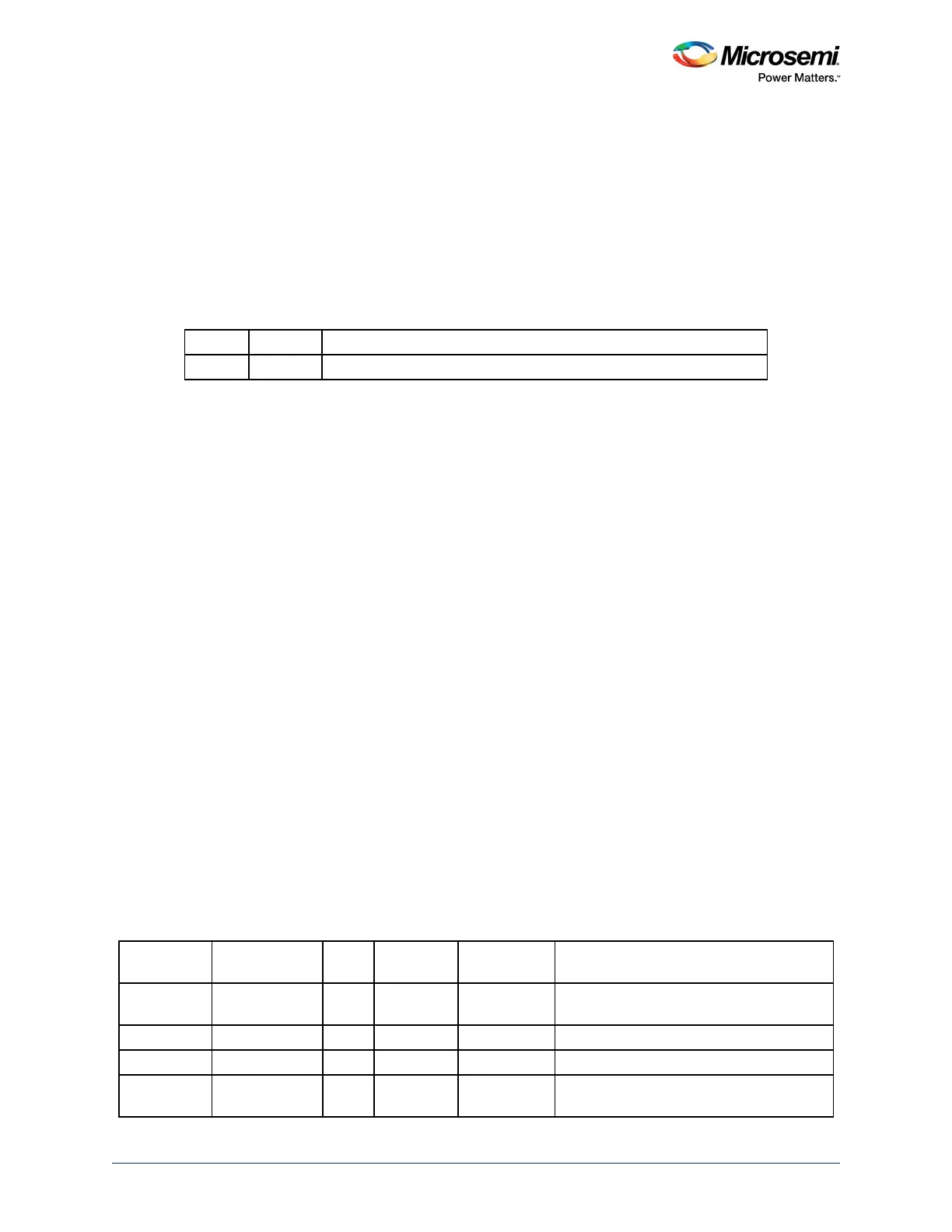
Table 71 • System Timer Registers Summary
Address Name Type
Required
Privilege Reset Value See
0xE000E010 SYST_CTRL RW Privileged 0x00000004 SysTick Control and Status Register,
page 120
0xE000E014 SYST_RVR RW Privileged 0x00000000 SysTick Reload Value Register, page 120
0xE000E018 SYST_CVR RW Privileged 0x00000000 SysTick Current Value Register, page 121
0xE000E01C SYST_CALIB RO Privileged
0xC0000000
1
SysTick Calibration Value Register,
page 121