Peripheral DMA
UG0331 User Guide Revision 15.0 265
9.2 Functional Description
This section provides the detailed description of the PDMA.
9.2.1 Architecture Overview
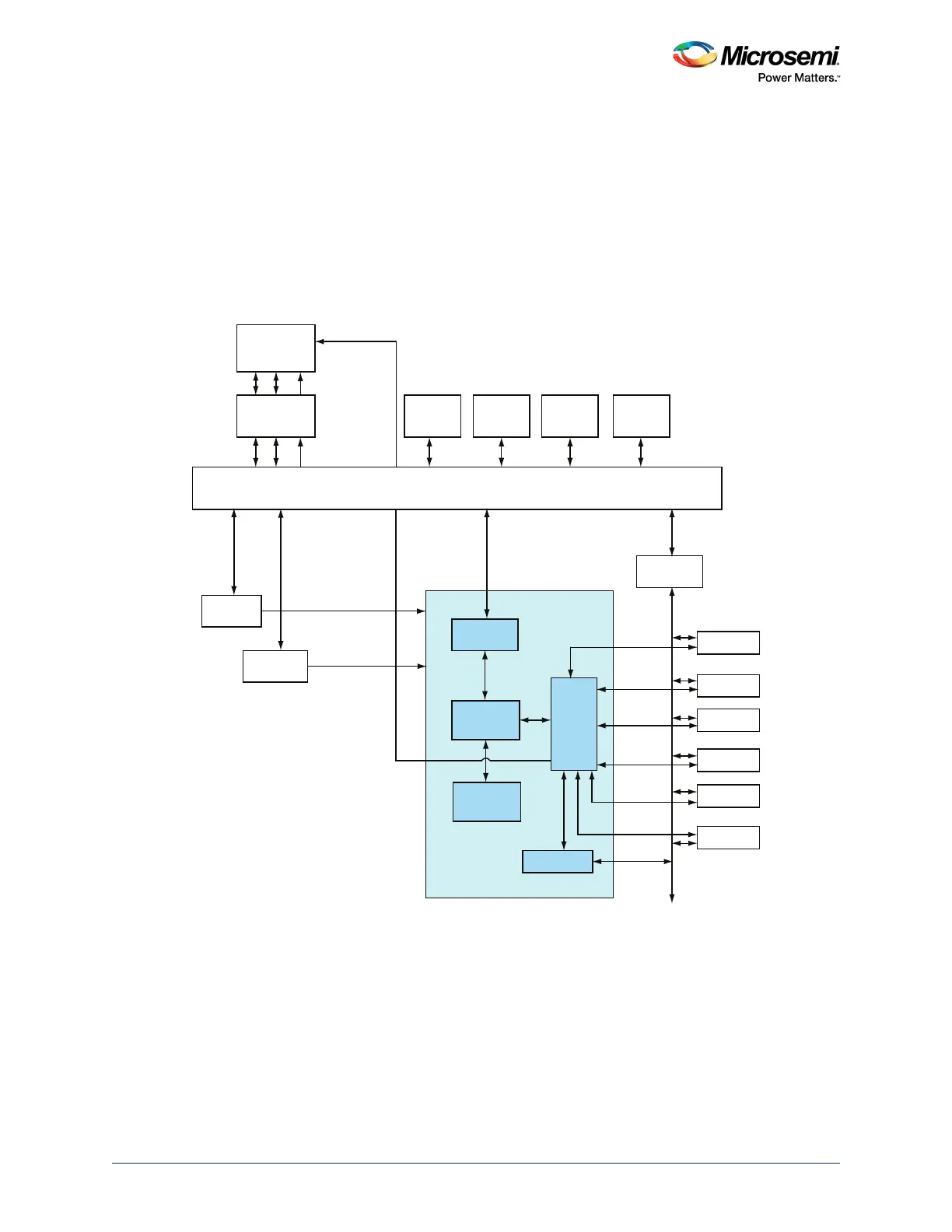
The PDMA controller mainly consists of the following blocks, as shown in the following figure.
• AHB and APB Interfaces
• 8-Channel DMA Controller
• Timing and Control
• Channel Arbiter
Figure 130 • PDMA Internal Architecture
9.2.1.1 AHB and APB Interfaces
As shown in the preceding figure, the PDMA has two interfaces—AHB-lite and APB. The APB interface
is a 32-bit APB slave used for configuring the PDMA. DMA operations do not occur on the APB bus
interface of the PDMA. The PDMA performs single cycle accesses on the AHB interface only and Burst
mode is not supported.
AHB Bus Matrix (10x7)
Cache
Controller
SD IC
ARM Cortex-M3
Processor
PDMAINTERRUPT
DMA_READY_1[1:0]
DMA_READY_0[1:0]
RxRDY
and TxRDY
RxRDY
and TxRDY
RxRDY
and TxRDY
OUTREADY
and INREADY
SPIRXAVAIL
and TxRFM
SPIRXAVAIL
and TxRFM
Microcontroller Subsystem (MSS)
PDMA
SD I
AHB To APB
Bridge
SPI_0
SPI_1
MMUART_0
COMM_BLK
CAN
MMUART_1
FIC_0
FIC_1
IDC
DS
eNVM_0
AHB
Controller
eNVM_1
AHB
Controller
eSRAM_1
AHB
Controller
eSRAM_0
AHB
Controller
AHB
Interface
Timing
and
Control
APB Interface
8 DMA
Channels
Channel
Arbiter