Communication Block
UG0331 User Guide Revision 15.0 593
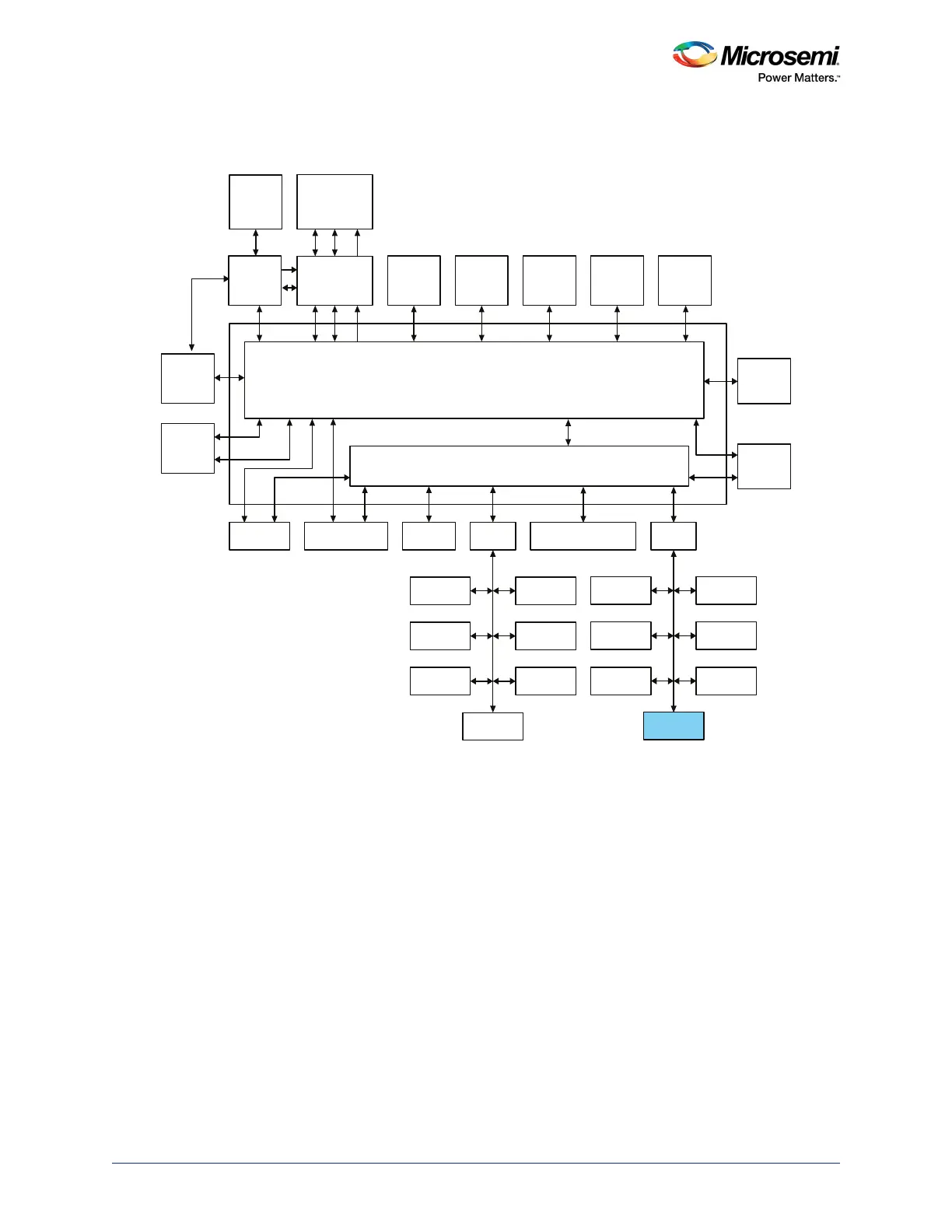
The following figure depicts the connectivity of COMM_BLK to the advanced high-performance bus
(AHB) matrix.
Figure 250 • Interfacing of COMM_BLK with AHB Bus Matrix
17.2 Functional Description
This section provides details of the COMM_BLK subsystem.
17.2.1 Architecture Overview
The COMM_BLK consists of an APB interface, 8 byte transmit FIFO, and an 8 byte receive FIFO. There
is one COMM_BLK instantiated in the MSS and one in the system controller; each can communicate with
the other. Whenever the Cortex-M3 processor writes a character into the COMM_BLK, it is transmitted to
the receiving side of the COMM_BLK and an interrupt is asserted to the system controller.
AHB Bus Matrix
MS5 MM8
eSRAM_0 eSRAM_1eNVM_0 eNVM_1
System
Controller
Cache
Controller
SD IC
ARM Cortex-M3
Processor
SD I
MSS DDR
Bridge
PDMA
MS0 MS1MS3MS2MM9MM0MM1MM2MS6
MM3
MM7
USB OTG
AHB To AHB Bridge with Address Decoder
APB_0 APB_1
FIC_2 (Peripheral
Initialization )
SYSREG
Triple Speed
Ethernet MAC
FIC_1
MM4 MS4
MM5 MM6
IDC
D/S
MMUART_0
SPI_0
I2C_0
PDMA
Configuration
WATCHDOG
FIIC
TIMERx2
MMUART_1
SPI_1
I2C_1
CAN
GPIO
RTC
COMM_BLK
HPDMA
FIC_0
MDDR
MS 5_F I C
MS5_MAC
MS5_ SR MS5_ APB 0 M S5_ FIC2 MS5 _APB 1
MS 5_ USB
Microcontroller Subsystem (MSS)